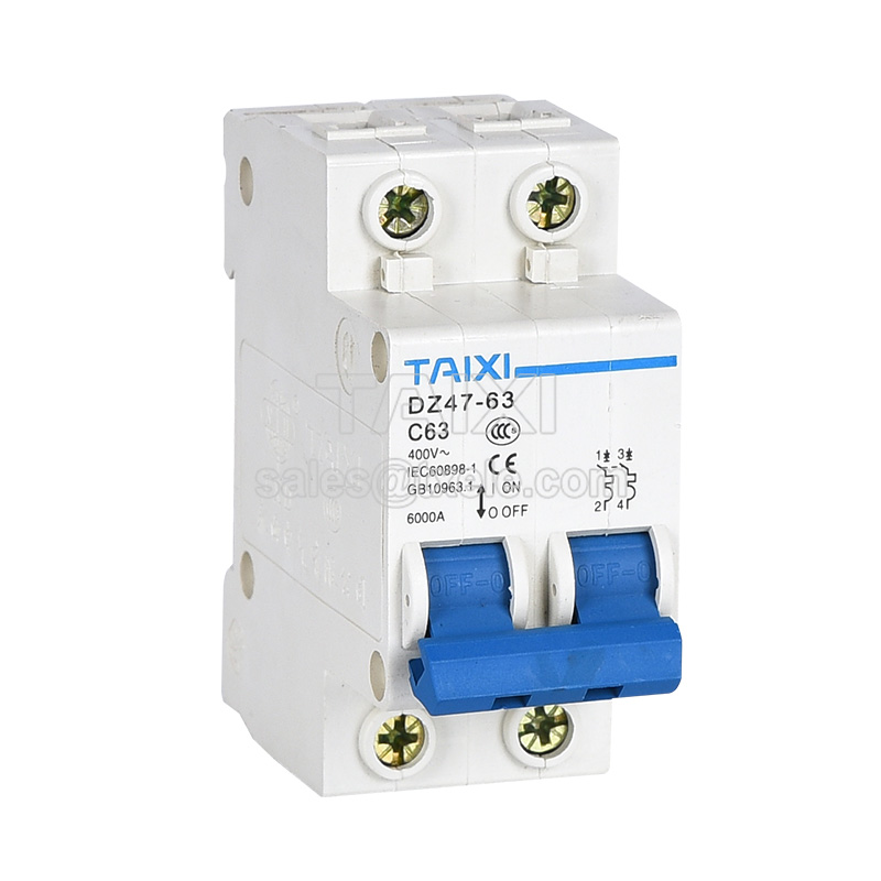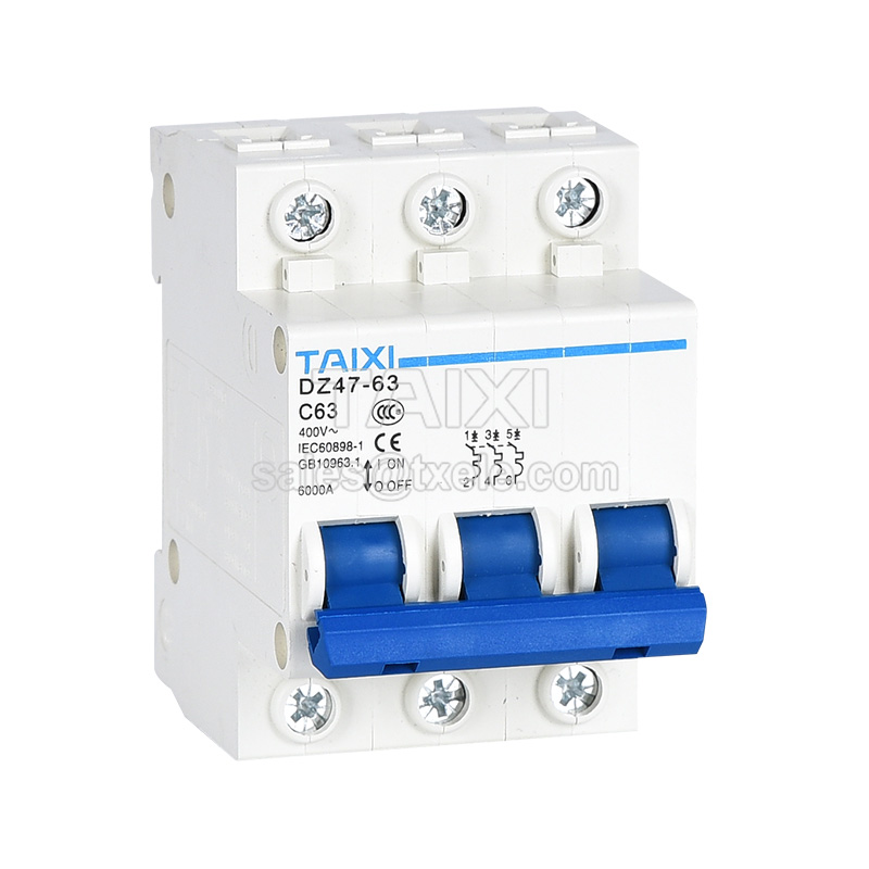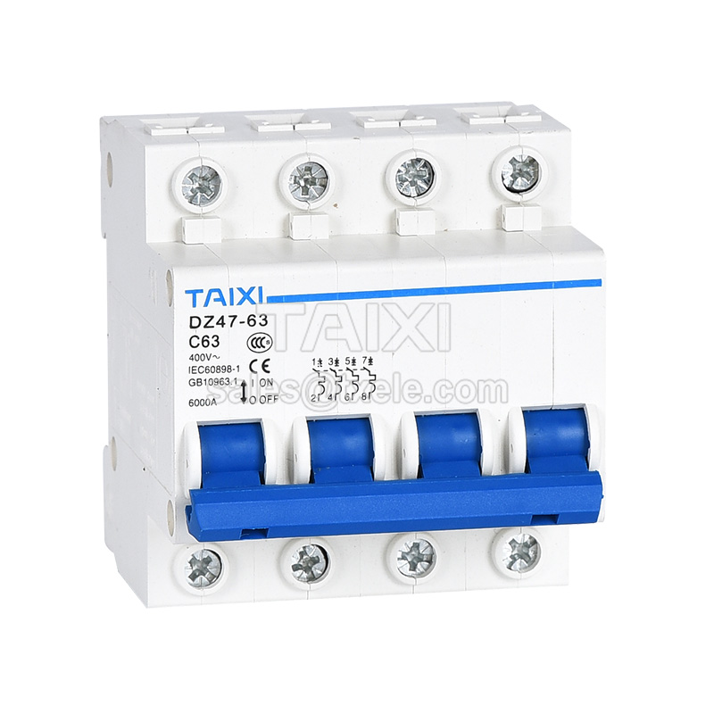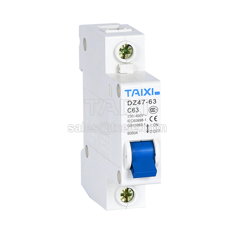


DZ47-63 Circuit Breaker (3KA/4KA MCBs)
Miniature Circuit Breaker | MCB
![]()
Parameters
Details
Size&weight
Related
Video
Message
SCOPE OF APPLICATION
DZ47-63 miniature circuit breaker is mainly used in the AC 50 / 60Hz, rated operating voltage of 230V / 400V and below, rated current of 63A circuit, the circuit breaker is mainly used in electrical wiring of modern buildings and overload, short circuit protection of equipment, also applies to infrequent operation and isolation of the line. Structural features of DZ47-63 MCB is composed of the plastic casing, operating mechanism, contact arc system, trip mechanism and other components. The casing uses a special plastic with high flame retardant and high strength, it has high impact resistance and light-weight. The parts of the operating mechanism of MCB are made of high-strength plastic, which ensures the sensitivity and reliability while obtaining the lowest moment of inertia so that the time from the short circuit fault to the trip mechanism operation is short. The tripping mechanism is composed of a bimetal over-load reverse-time trip mechanism and a short-circuit instantaneous electromagnetic mechanism. Contact arc system uses a special guide arc angle and aisle off room, and has significant current limiting characteristics.
The product complies with IEC60898 and GB10963.1 Standard requirements. DZ47-63miniature circuit breakers produced by DIHOOL have been certified by the national CCC and CE
NORMAL OPERATING CONDITIONS AND INSTALLATION CONDITIONS
The upper limit of ambient temperature does not exceed +40 °C, the lower limit does not less than -5°C, and the average temperature of 24h does not exceed +35 °C.
Altitude of the installation site should not exceed 2000m.
Atmospheric relative humidity at ambient air temperature +40°C is not more than 50%, it allowed to have a higher relative humidity at lower temperatures; for example at + 20°C up to 90%. Special precautions should be taken for condensation that may occasionally occur on the product due to temperature changes.
Pollution Degree: Grade 2.
Installation conditions: Installed in a place without significant impact, vibration, non-hazardous (explosive) medium.
Installation: TH35-7.5 installation rail.
Installation category: Class II, III.
| Electrical Features | |
| Rated Current | Rated Current |
| Poles | 1P 2P 3P 4P |
| Rated Voltage Ue | 90V-125V 200-400V |
| Insulation Volage Ui | 500V |
| Rated Frequency | 50/60Hz |
| Rated Breaking Capacity | 4000A |
| Rated Impulse Withstand Voltage Uimp | 6kV |
| Dielectric Test Voltage At And Ind. Freq.For 1min | 2kV |
| Thermo-Magnetic Release Characteristic | B (3In ~ 6In); C (5In ~ 10In); D (10In ~ 20In). |
| Electrical Life | 4000 |
| Mechanical Life | 20000 |
| Installation | |
| Contact Position Indicator | YES |
| Protection Class | IP20 |
| Reference Temperature For Setting Of Thermal lement | 30°C |
| Ambient Temperature(With Daily Average (35°C) | -5°C~40°C |
| Storage Temperature | -25°C~+70°C |
| Terminal Connection Type | Phillips Screws |
| Suitable For Cable Cross-Section | 6-63A 1.5-25MM²;80-125A 4-35MM² |
| Tightening Torque | 2.5-3.0N.m |
| Mounting | 35MM DIN Rail or M4 Side Mounted |
| Combination With Accessories | |
| Auxillary Contact | DZ47-OF |
| Alarm Contact | DZ47-SD |
| Shunt Release | DZ47-MX(DC24V / AC230V) |
| UnderVoltage And UnderVoltage Release | DZ47-MV+MN(AC230V / AC380V) |
| LossVoltage Release | DZ47-MNs |
| Shunt Release + Auxiliary Contact | DZ47-MX+OF(DC24V / AC230V) |
TECHNICAL PARAMETERS
| Trip Type | Rated Current | Rated short-circuit breaking capacity A |
COSΦ |
| C | 1≤In≤40 | 6000 | 0.65~0.70 |
| C | 40<In≤63 | 4000 | 0.75~0.80 |
| D | 1≤In≤63 | 4000 | 0.75~0.80 |
7.3 Over-current protection characteristics under the ambient temperature of 30 D~35
| No. | Trip type | Rated Current In | Test current A | Appointed time | Expected result | Initial state |
| 1 | C、D | All values | 1.13In | t≤1h | Non tripping | Cold |
| 2 | C、D | All values | 1.45In | t<1h | Tripping | Immidiately after the last test |
| 3 | C、D | ≤32 | 2.55In | s<t<60s | Tripping | Cold |
| >32 | 1s<t<120s | |||||
| 4 | C | All values | 5In | t≤0.1s | Non tripping | Cold |
| D | 10In | |||||
| 5 | C | All values | 10In | t≤0.1s | Tripping | Cold |
| D | 20In |
TRIPPING CHARACTERISTIC CURVE

| Product | Model | Rated Voltage Un |
Drop away voltage | Application |
| Overvoltage Release |
MV | 230V | value of overvoltage Uwo=270V±5% |
To make the circuit breaker tripping and achieve over-voltage protection of the line when the power supply voltage rises to 270V±5% |
| Undervoltage Release |
MN | 230V | value of undervoltage Uoe=170V±5% |
To make the circuit breaker tripping and achieve under-voltage protection of the line when the power supply voltage falls between (0.35~0.75) Ue |
| overvoltage-undervoltage Release |
MV+MN | 230V | value of overvoltage Uw0=270V±5% value of undervoltage Uoe=170V±5% U08=170V±5% |
To make the circuit breaker tripping and protect the line when the 230V rated supply voltage rises to 270±5% or falls at 170V±5% to 270±5% or falls at 170V±5% |
| Loss of pressure release |
Mns | 230V | value of undervoltage U0e=170V±5% loss of pressure value Uoe=0 Release |
When the 230V rated voltage at 75% to 105%, the no-voltage release will pull in to make circuit breaker switch on; When the rated voltage at 40%. the no-voltage will release to make circuit breaker trip off. |
| Three-phase overvoltage- undervoltage +default phase |
MV+MN | 380V | value of overvoltage Uwo=460V±15 value of undervoltage Uo8=300V±15 |
To make the circuit breaker tripping and protect the line when the 380V rated supply voltage rises to 460±15 V or falls at 300±15V |
| Three-phase four-wire overvoltage-undervoltage |
GQ(MV+MN) | 230V | value of overvoltage Uo=270V±5% value of undervoltage U0e=170V±5% |
To make the circuit breaker tripping and protect the line when the 230V rated supply voltage rises to 270±5%or falls at 170±5%V |
| Shunt release | MX | AC230V | To make the circuit breaker tripping and protect the line when the control voltage exceeds the rated voltage of 70% to 110% |
|
| DC24V | ||||
| Shunt release +Auxiliary contact |
MX+OF | AC230V | Long-distance breaks circuit. and to control the auxiliary circuit by auxiliary contacts Long-distance breaks circuit. and to control the auxiliary circuit b the micro-switch. |
|
| DC24V | ||||
| Alarm contact | SD | 115/230/400V | 1.3A | To provide alarm signal when the circuit breaker breaking due to protective circuits'fault |
| Auxiliary contact | OF | 115/230/400V | 1.3A | To provide auxiliary signal and control auxiliary circuit |
MODEL MEANING AND MAIN TECHNICAL PARAMETERS
| Circuit Breaker Accessory | Rated insulation voltage Ui |
Rated control supply voltageUs |
Release power wastage(W or VA) |
Pull-in voltage | |
| MX+OF Shunt release+ Auxiliary contact |
415V | AC/DC:220~380V:110-220V | 240 | (0.7-1.1)Us | |
| AC/DC:24-48V | 120 | ||||
| MX+OF Shunt release+ Auxiliary contact |
active | 415V | AC/DC:220~380V:110-220V | 240 | (0.7-1.1)Us |
| AC/DC:24-48V | 120 | ||||
| passive | 415V | AC/DC:220~380V:110-220V | 240 | (0.7-1.1)Us | |
| AC/DC:24-48V | 120 | ||||
| MX Shunt release | 415V | AC/DC:220~380V:110-220V | 240 | (0.7-1.1)Us | |
| AC/DC:24-48V | 120 | ||||
Outline And Installation Dimensions
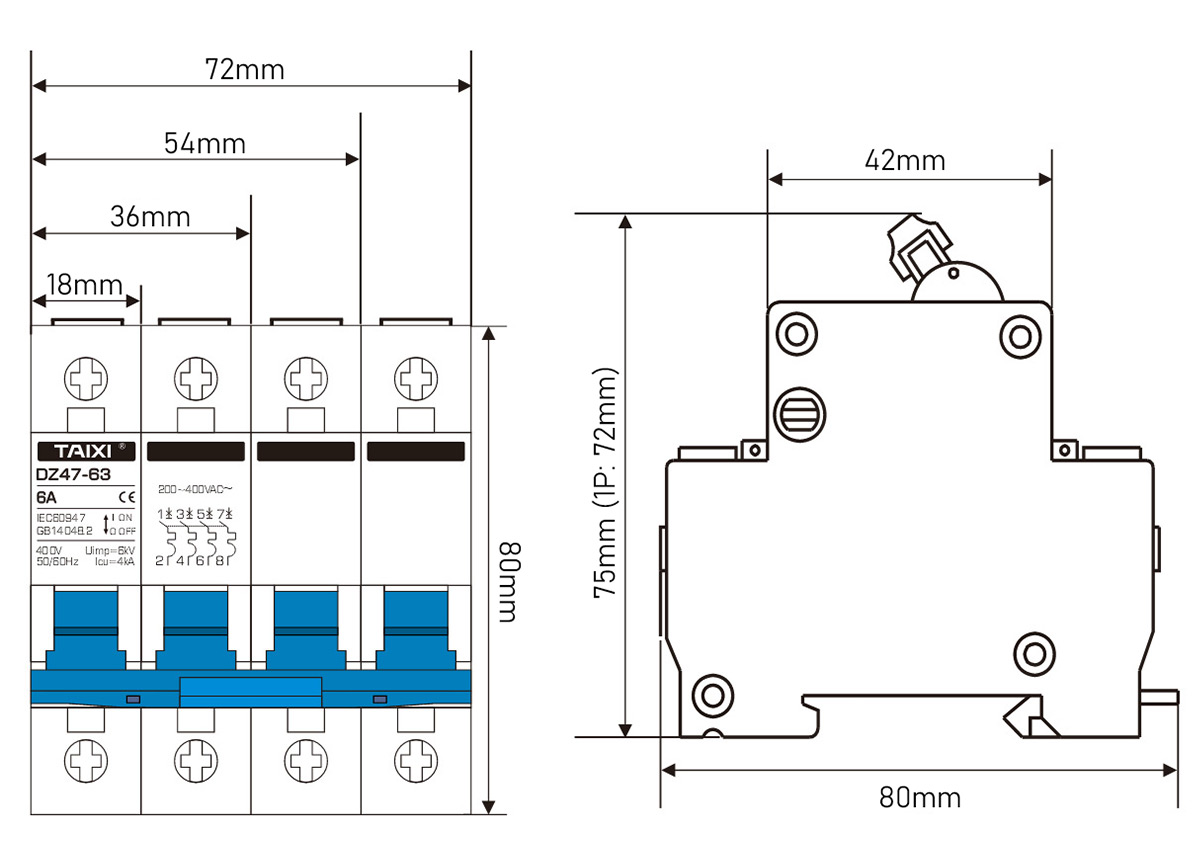
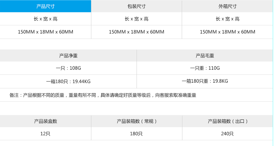
view and download
| File name(Click to view) | File type | file size | View times | Click to download |
| gag | image/jpeg | 14kb | 0 |
Product related news
| News title | Promulgator | Release time | View times | Click to read |


