


DZ47S-63 Circuit Breaker (Controllable MCBs)
Miniature Circuit Breaker | MCB


Parameters
Details
Size&weight
Related
Video
Message
SCOPE OF APPLICATION
DZ47S Miniature Circuit Breaker with shunt trip, suitable for AC 50Hz and 60Hz, rated voltage 230 / 400V, rated current 125A of the line, remote control and automatic signal breaking control for the circuit, is mainly used for over-load and short-circuit protection in circuits. And infrequent transfer between circuits in normal condition. Currently widely used in IC card prepaid watt-hour meter to control on-off of lines. DZ47S Circuit Breaker with shunt trip has a small size, easy installation, etc., controls residential charged meter, when the IC card recharge balance is insufficient, the control circuit breaker will automatically disconnect to play the role of power outages, and users can close the circuit after recharging. Main functions: overload protection, short circuit protection, isolation, accept the IC card power meter signal to cut off the circuit. DZ47S Miniature Circuit Breakers with shunt trip meet standards of IEC60898, GB10963, GB14048.2, with the international advanced level.
WORKING AND INSTALLATION CONDITIONS
The ambient air temperature is -5°C+40°C, and the average temperature within 24h does not exceed +35°C. The altitude of the installation site should not exceed 2000m. The relative humidity of the atmosphere should not exceed 50% when the ambient air temperature is +40°C, and a higher relative humidity is allowed at lower temperatures; special measures should be taken for occasional moderate condensation due to temperature changes. Pollution degree: Class 2. The inclination of the installation plane to the vertical plane should not exceed ±5°. Installation conditions: Install in a place without obvious shaking and impact vibration, in a medium without danger of explosion, and there is no gas and conductive dust in the medium enough to corrode metals and destroy insulation, and no place where rain and snow are attacked. Installation method: use the standard installation rail (TH35-7.5 type) to install. When installing, it is generally installed vertically, and the handle upward is the power-on position. Installation category: Class III.
TECHNICAL PARAMETER
OVERCURRENT PROTECTION FEATURES
| Number | Rated current | Starting State | Test Current | Specified Time | Expected Outcome |
| 1 | All | cold | 1.13ln | t≤1h | no-trip |
| 2 | All | Immediately after the previous test | 1.45ln | t<1h | trip |
| 3 | ln<32 | cold | 2.55ln | 1s<t<60s | trip |
| ln>32 | 1s<t<120s | trip | |||
| 4 | All | cold | 5ln | t≤0.1s | no-trip |
| 10ln | t<0.1s | trip |
SHUNT TRIP CHARACTERISTICS
| Model | Rated Control Voltage | Action Time | cAction TimAction Time |
| DZ47S | 230V | 0.5s<t<2s | 3min |
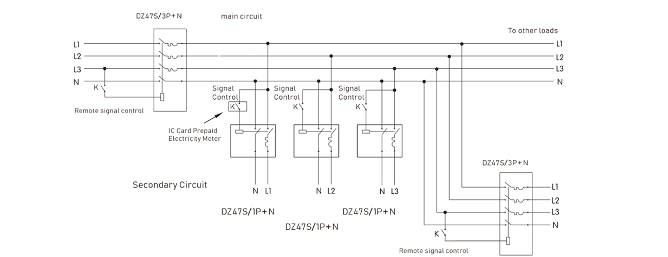
CONNECTION
| Rated current (A) | Minimum Adapter Copper Wire |
| 6 | 1 MM2/17AWG |
| 10 | 1.5 MM2/17AWG |
| 16 | 1.5 MM2/17AWG |
| 25 | 2.5 MM2/17AWG |
| 32 | 4 Mm2/11AWG |
| 40 | 6 Mm2/11AWG |
| 50 | 10 Mm2/11AWG |
| 63 | 10 Mm2/11AWG |
| 80 | 16MM2/5AWG |
| 100 | 25MM2/5AWG |
| 125 | 35MM2/5AWG |
TEMPERATURE COMPENSATION
When the ambient temperature is not a benchmark of 30 degrees , the reference correction factor is as folows.
| Ambient Temperature | -20℃ | -10℃ | 0℃ | 10℃ | 20℃ | 30℃ | 40℃ | 50℃ | 60℃ |
| Current Correction Coefficient | 1.25 | 1.2 | 1.15 | 1.10 | 1.05 | 1.00 | 0.95 | 0.90 | 0.85 |
CURRENT CORRECTION VALUES USED AT DIFFERENT AMBIENT TEMPERATURES
| Temperature(℃) corrected current value(A) Rated current(A) |
-25 | -20 | -110 | 0 | 10 | 20 | 30 | 40 | 50 | 60 |
| 10 | 12.5 | 12.4 | 11.9 | 11.3 | 10.8 | 10.4 | 10 | 9.7 | 9.2 | 8.5 |
| 16 | 20 | 19.8 | 18.9 | 18.1 | 17..3 | 16.5 | 16 | 15.5 | 14.6 | 13.8 |
| 20 | 25 | 24.8 | 23.6 | 22.6 | 21.1 | 20.6 | 20 | 19.4 | 18.2 | 17.2 |
| 25 | 31.25 | 31 | 29.5 | 28.3 | 27 | 25.8 | 25 | 24.3 | 22.8 | 21.3 |
| 32 | 40 | 39.7 | 37.8 | 36.2 | 34.6 | 33 | 32 | 31 | 28.8 | 27.2 |
| 40 | 50 | 49.6 | 47.2 | 45.2 | 43.2 | 40.8 | 40 | 38.4 | 37.2 | 35.2 |
| 50 | 63.5 | 62.5 | 59 | 56.5 | 54 | 51.5 | 50 | 48 | 45.5 | 43 |
| 63 | 80.01 | 78.8 | 74.3 | 71.2 | 68 | 64.9 | 63 | 60.5 | 57.2 | 54.2 |
| 80 | 100 | 95.4 | 90 | 86 | 84 | 82 | 80 | 74 | 70 | 65 |
| 100 | 120 | 114.2 | 112 | 110 | 106 | 103 | 100 | 94 | 88 | 80 |
| 125 | 150 | 140 | 138 | 135 | 130 | 127 | 125 | 115 | 105 | 90 |
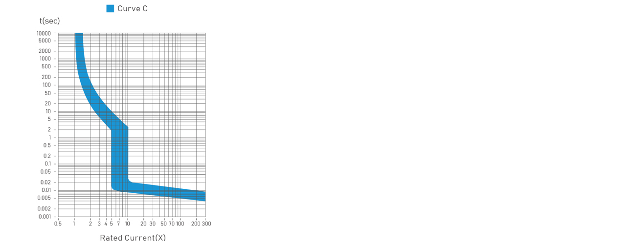
TRIPPING CHARACTERISTIC CURVE -- C TYPE
STRUCTURE FEATURES
This circuit breaker is assembled by DZ47 miniature circuit breaker and signal control release.
DZ47S miniature circuit breaker is mainly composed of insulating shell, operating system, contact system, thermal magnetic system and arc extinguishing system. The signal control release is composed of a signal input port, a signal voltage detection circuit, a delay control circuit and a tripping mechanism. The plastic case circuit breaker and the signal control release are linked by push rods.
working principle:
When in use, add a control voltage to the signal control release of the circuit breaker through the signal input port, that is, the signal voltage (which can be provided by the remote control circuit), and then push the handle of the circuit breaker to the closed position, and drive the moving contact to the closed position through the operating mechanism. The static contact is running and is in reliable contact with the static contact, and the line is connected at this time. When an overload fault occurs in the line, the overload current makes the bimetallic element bend, the overload release acts, and pushes the locking mechanism to act, thereby realizing the breaking of the line. When a short-circuit fault occurs in the line, the short-circuit current causes the instantaneous release to act, and pushes the locking mechanism to act to realize the breaking function. When the line must be cut off immediately due to certain needs, the control voltage can be cut off through the remote control system. At this time, after the signal voltage detection circuit gets the signal, it outputs a voltage signal to the trip coil, and pushes the locking mechanism to act to realize the breaking function. Therefore, the product can achieve the purpose of breaking under different line conditions.
The circuit breaker is equipped with a shunt tripping device, which has the following characteristics:
The opening and closing neutral pole is connected first and then disconnected than the overcurrent protection pole;
High rated breaking capacity, up to 6kA;
The circuit breaker operating mechanism is a free release mechanism with energy storage, and the contacts are quickly closed, which overcomes the adverse effects caused by the speed of manual operation of the handle, and greatly improves the service life of the product; during normal operation, the contacts can only stay in the closed or open position;
The shunt release is composed of thyristor, electromagnetic release and other driving elements;
The shell and components are made of high flame retardant, high temperature and impact resistant plastic.
HOW IT WORKS
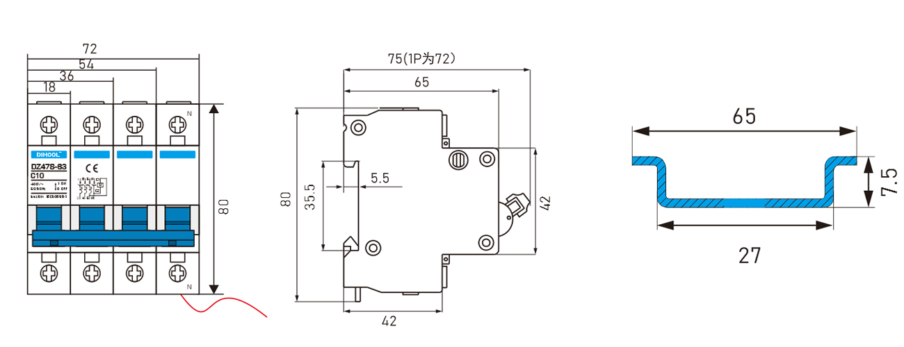
OUTLINE AND INSTALLATION DIMENSIONS

view and download
| File name(Click to view) | File type | file size | View times | Click to download |
Product related news
| News title | Promulgator | Release time | View times | Click to read |