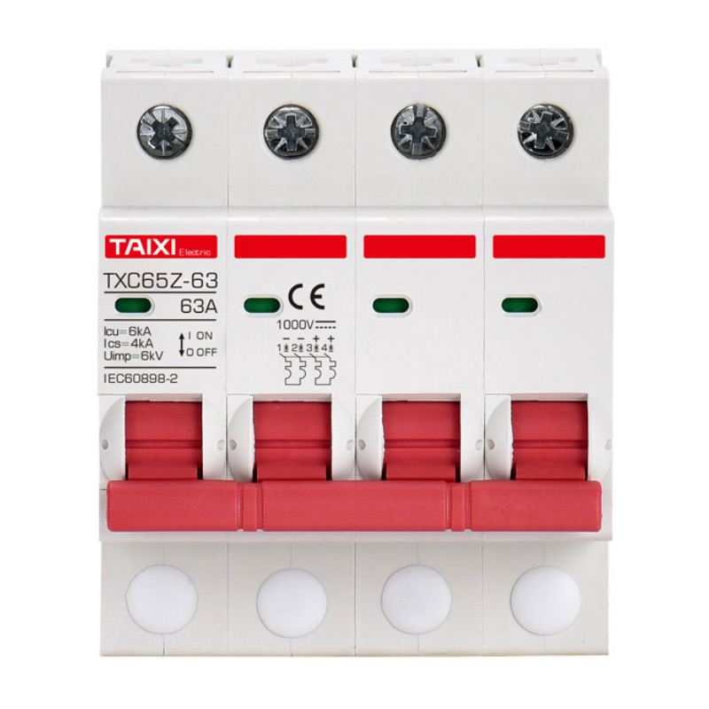


TXC65Z-63 DC Miniature Circuit Breaker
Solar Disconnect Switch
![]()
Parameters
Details
Size&weight
Related
Video
Message
SCOPE OF APPLICATION
TXC65Z-63 DC miniature circuit breaker is suitable for the circuit of AC 50 / 60Hz, rated voltage of 230 / 400V, rated current of 63A, or the circuit of DC voltage of 220V, rated DC current of 63A, to protect overload and short circuit, and infrequent transfer between circuits under normal circumstances, also be used as the isolating switch for cut-off circuit to maintain circuit and equipment.
TXC65Z-63 DC miniature circuit breaker has the functions of overload protection, short circuit protection, control and isolation. It is mainly used in DC power supply system, ship electric power system and electric propulsion system, PV power system and other places.
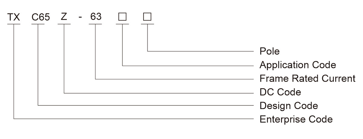
MODEL AND MEANING

MAIN TECHNICAL PARAMETERS
| Rated Current | 1A, 2A, 4A, 6A, 10A, 16A, 20A, 25A, 32A, 40A, 50A, 63A |
| Frame Rating | 63A |
| Poles | 1P / 2P / 3P / 4P |
| Rated Working Voltage | DC125V / DC250V / DC500V / DC1000V |
| Rated Impulse Withstand Voltage Uimp | 6kV |
| Breaking Capacity | 4.5kA |
| Current Limit Level | 3 |
| Protection Class | IP20 |
| Quick Closure | To ensure reliable work of the impact load, to extend the electrical life of the circuit breaker |
| Electrical Life | 1000 Times |
| Mechanical Life | 10000 Times |
| Ambient Temperature | -30°C~+70°C |
| Resistance To Heat And Humidity | Class 2 (Temperature 55°C, Relative Humidity 95%) |
| Elevation | Not more than 2000M |
| Adapter Cable | 1 ~ 32A: 25mm² and below, 40 ~ 63A: 35mm² and below |
| Installation | no significant vibration and shock place, tunnel-type terminals, wiring of DC circuit breaker, please pay attention to polarity, modular structure, easily installed in the TH35-7.5 DIN standard rail, 1 ~ 32A: 2.5 N , 40-63A: 3.5N. |
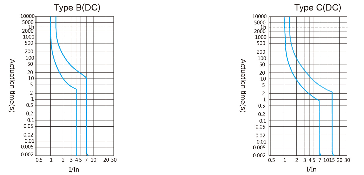
| Tripping Characteristics | Type C curve, instantaneous trip range (6.8 ~ 10.2) In, protect the normal load and power distribution cable; Type B curve, instantaneous trip range (4.4 ~ 6.6) In, protect the load of smaller short circuit current. |
| Standards | IEC60898-2 / GB10963.2 |
| Certification | CCC, CE |
Connection Example
| Poles | 1P | 2P | 3P | 4P |
| Breaking Capacity | 4.5kA | 4.5kA | 4.5kA | 4.5kA |
| Un (Rated Voltage) | 125V/250V | 250V/500V | 250V/500V | 1000V |
| Unmax UL+/L- | 125V/250V | 250V/500V | 250V/500V | 1000V |
| Unmax UL/↓ | 125V/250V | 250V/500V | 250V/500V | 1000V |

Remark: (1) L+: power supply positive pole, L-: power supply negative pole;
(2) +: the circuit breaker positive pole, -: circuit breaker negative pole;
(3) In DC power supply "L-" is usually grounded, in the positive and negative power system, neutral pole "M" adopts ground installation
MAIN TECHNICAL PARAMETERS
According to the type of instantaneous release
| Tripping Form | AC Range | DC Range |
| B | 3In | 4.4In |
| C | 5In | 6.8In |
Rated Short-Circuit Breaking Capacity
| Rated Current (A) | Poles | Rated Voltage (V) | Rated Short-Circuit Current (A) | Operation Short-Circuit Current (A) |
| 1~63 | 1 | 220 | 3000 | 3000 |
| 2~4 | 4500 | 3000 |
Mechanical Electrical Life
| Category | Times | Operation Frequency (times/hour) | Rated Current |
| Electrical life | 1000 | 240 | 1~32A |
| 120 | 40~63A | ||
| Mechanical life | 10000 | 240 | 1~63A |
Mechanical Electrical Life
| No. | Curve | Rated Current (A) | Initial State | DC | Set Time | Result | Remark |
| a | B, C | 1~63 | Cold | 1.13In | t≤1h | Non Tripping | |
| b | B, C | 1~63 | After the last | 1.45In | t<1h | Tripping | The current rise steadily to a fixed value within 5S |
| c | B, C | In≤32A | Cold | 2.55In | 1s<t<60s | Tripping | |
| In>32A | 1s | ||||||
| d | B | 1~63 | Cold | 4In | 0.1s≤t≤45s (In≤32A) | Tripping | |
| C | 7In | 0.1s≤t≤15s (In≤32A) | |||||
| e | B | 1~63 | Cold | 7In | t<0.1s | Tripping | |
| C | 15In |
Tripping Characteristic Curve

Wiring: 25mm² and below for wire connection, wiring method is screws to tighten the wiring, the torque is 2.5N · m.
| Rated Current In (A) | Copper Conductor Nominal Cross-Sectional Area (mm²) |
| 1~6 | 1 |
| 10 | 1.5 |
| 16, 20 | 2.5 |
| 25 | 4 |
| 32 | 6 |
| 40, 50 | 10 |
| 63 | 16 |
Power consumption per pole of the circuit breaker
| Rated Current In (A) | Maximum power consumption per pole (W) |
| 1~10 | 2 |
| 16~32 | 3.5 |
| 40~63 | 5 |
Structural Features
High rated short-circuit breaking capacity.
Double wiring function, the outlet terminal can easily connect with the standard bus and hard-soft wire, incoming terminal can connect with the hard-soft wire.
With red and green safety instructions, higher security.
Mechanism with the energy storage operation, rapid contact closure, overcomes adverse effect of speed of the manually operated handle, and greatly improves the product life.
The terminals have the forked tail with function of preventing false wiring, which improves wiring efficiency and reliability.
Products can be used with a variety of modular accessories, such as S9, V9, XF9, XF9J.
Case and other plastic parts are made of plastic of high flame retardant, high temperature and impact resistant.
Current correction factor used at different altitudes
| Trip Type | Rated Current (A) | Current Correction Factor | Example | ||
| 2 | ≤2000m | (2000~3000)m | ≥3000m | ||
| B, C | 3.5 | 1 | 0.9 | 0.8 | Rated current used after the product of rated current of 20A derates capacity in 3000m: 0.8x20=16A |
| Temperature(℃) corrected current value(A) Rated current(A) |
-35 | -30 | -20 | -10 | 0 | 10 | 20 | 30 | 40 | 50 | 60 | 70 |
| 1 | 1.3 | 1.26 | 1.23 | 1.19 | 1.15 | 1.11 | 1.05 | 1 | 0.96 | 0.93 | 0.88 | 0.83 |
| 2 | 2.6 | 2.52 | 2.46 | 2.38 | 2.28 | 2.2 | 2.08 | 2 | 1.92 | 1.86 | 1.76 | 1.66 |
| 3 | 3.9 | 3.78 | 3.69 | 3.57 | 3.42 | 3.3 | 3.12 | 3 | 2.88 | 2.79 | 2.64 | 2.49 |
| 4 | 5.2 | 5.04 | 4.92 | 4.76 | 4.56 | 4.4 | 4.16 | 4 | 3.84 | 3.76 | 3.52 | 3.32 |
| 6 | 7.8 | 7.56 | 7.38 | 7.14 | 6.84 | 6.6 | 6.24 | 6 | 5.76 | 5.64 | 5.28 | 4.98 |
| 10 | 13.2 | 12.7 | 12.5 | 12 | 11.5 | 11.1 | 10.6 | 10 | 9.6 | 9.3 | 8.9 | 8.4 |
| 16 | 21.12 | 20.84 | 20 | 19.2 | 18.4 | 17.76 | 16.69 | 16 | 15.36 | 14.88 | 14.24 | 13.44 |
| 20 | 26.4 | 25.6 | 25 | 24 | 23 | 22.2 | 21.2 | 20 | 19.2 | 18.6 | 17.8 | 16.8 |
| 25 | 33 | 32 | 31.25 | 30 | 28.75 | 27.75 | 26.5 | 25 | 24 | 23.25 | 22.25 | 21 |
| 32 | 42.56 | 41.28 | 40 | 38.72 | 37.12 | 35.52 | 33.92 | 32 | 30.72 | 29.76 | 28.16 | 26.88 |
| 40 | 53.2 | 51.2 | 50 | 48 | 46.4 | 44.8 | 42.4 | 40 | 38.4 | 37.2 | 35.6 | 33.6 |
| 50 | 67 | 65.5 | 63 | 60.5 | 58 | 56 | 53 | 50 | 48 | 46.5 | 44 | 41.5 |
| 63 | 83.79 | 81.9 | 80.01 | 76.68 | 73.71 | 70.56 | 66.78 | 63 | 60.48 | 58.9 | 55.4 | 52.29 |
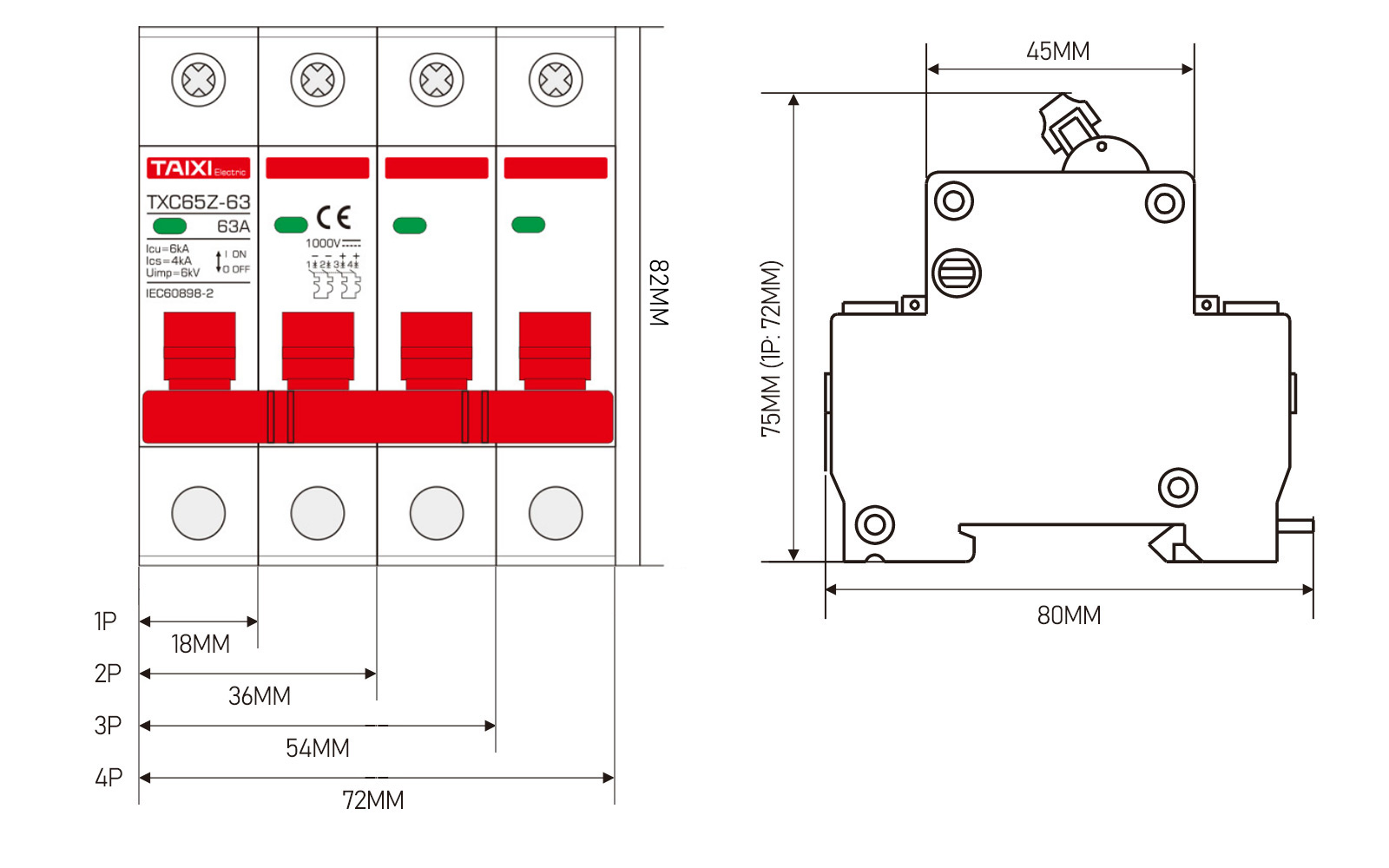
Outline And Installation Dimensions

view and download
| File name(Click to view) | File type | file size | View times | Click to download |
Product related news
| News title | Promulgator | Release time | View times | Click to read |


