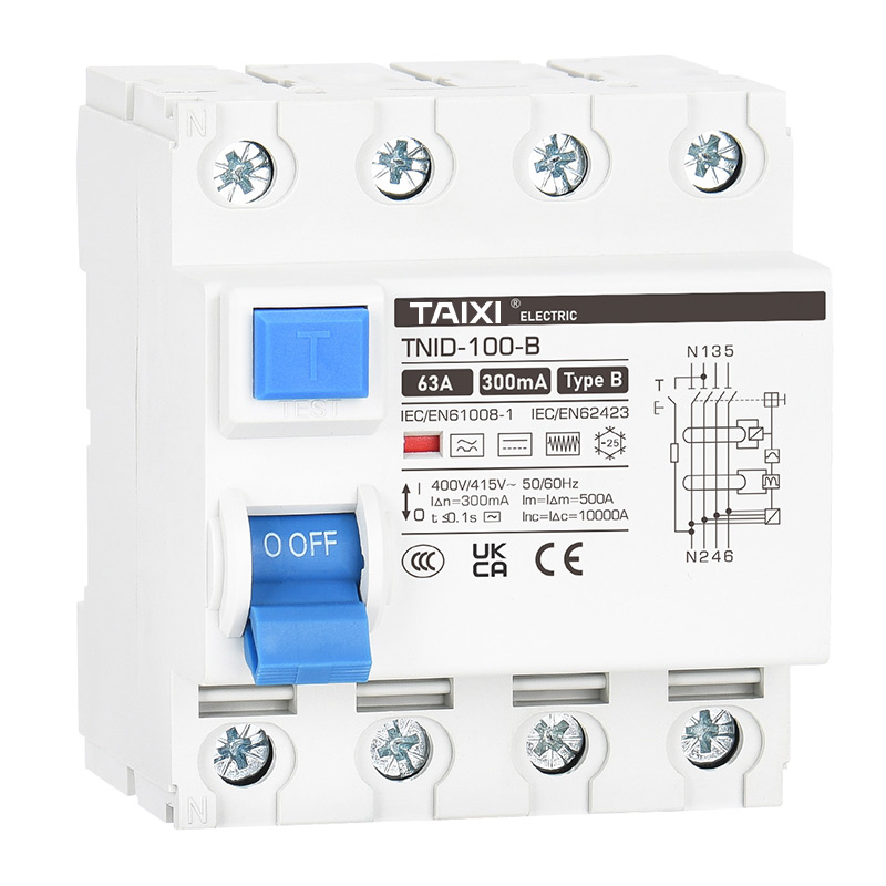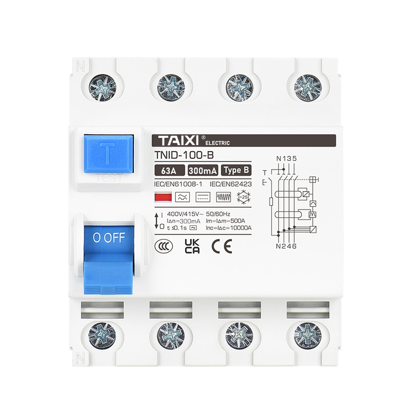


TNID-B Residual Current Circuit Breaker
Residual Current Circuit Breaker | RCCB-RCBO
![]()
Parameters
Details
Size&weight
Related
Video
Message
INTRODUCTION
TNID-63 Residual Current Circuit Breaker RCD Electromagnetic Type (without overcurrent protection) is suitable for AC rated voltage 1P+N 240V and 3P+N 400V, rated current up to 100A, The types of leakage tripping are divided into AC type, A type, and B type. When personal shock or power grid leakage current exceeds the specified value, the residual current action circuit breaker can quickly cut off the faulty power supply in a very short time. Protect the safety of human body and electrical equipment, can also be used for infrequent conversion of the line starting. Products are suitable for industrial, commercial, high-rise and residential and other places.Comply with the standards: GB 16916.1, IEC 61008-1, CCC, CE certification.Residual current circuit breaker according to GB16916.1 "Household and similar applications without overcurrent protection of residual current action circuit breaker (RCCB) Part 1: General rules" design, manufacturing and inspection.
INTRODUCTION
The elevation of the installation site shall not exceed 2000m.
Ambient air temperature: the upper limit of ambient air temperature shall not exceed +40°C; The average ambient air temperature for 24h does not exceed +35°C. The lower limit of ambient air temperature shall not be lower than -5°C.
Atmospheric conditions: When the maximum temperature is +40°C, the relative humidity of the air does not exceed 50%. At a lower temperature, a higher relative humidity is allowed, such as 90% at 20°C. Special measures should be taken for the occasional condensation caused by temperature changes.
Pollution level: 2
Installation conditions: Installed in a place without shock, vibration and rain or snow attack: the upper terminal is connected to the power side, and the lower terminal is connected to the load side; The inclination to the vertical plane shall not exceed 2°. Use TH35-7.5 steel mounting rail for installation.
Installation category: Ⅱ, Ⅲ.
The external magnetic field near the place where the circuit breaker is installed shall not exceed 5 times of the earth magnetic field in any direction.
ELECTRICAL TECHNICAL PARAMETERS
| Residual Current Protection Type | Electromagnetic |
| Standards | IEC 62423, IEC 61008.1 |
| Rated Current In | 16A, 20A, 25A,40A,63A,100A |
| Poles | 3P+N |
| Sensitivity | 15mA, 30mA, 100mA, 300mA |
| Residual Current Working Type | Type B |
| Rated Voltage Ue | 230V (1P+N), 440V (3P+N) |
| Rated Frequency | 50Hz / 60Hz |
| Residual Making And Breaking Capacity IΔm | 1500A |
| Short Circuit Current Inc=IΔc | 10000A |
| SCPD Fuse | 10000 |
| Rated Impulse Withstand Current 1.2/50µs | 6000V |
| Mechanical Working Life | 4000 Times |
| Electrical Life | 2000 Times |
| Rated Insulation Voltage Ui | 500V (1P+N), 900V (3P+N) |
| Dielectric test voltage at and ind. Freq. for 1min | 2.5kV |
| Pollution Degree | II |
| Break Time Under IΔn | ≤0.1s |
| Degree of Protection | IP20 |
| Contact Flag Indication | White for ON, Red for OFF |
| Ambient Temperature | -25°C to +40°C |
| Storage Temperature | -55°C to +70°C |
| Installation | DIN Rail IEC/EN 60715 |
| Wiring | 1.5 mm² - 25 mm² |
| Tightening Torque | 3.5*N.m |
| Connection | Up input and down output |
Break Time Of Residual Current Action
| In (A) | I△n (A) | Maximum Break Time And Minimum No-Drive Time | |||
| I△n | 2I△n | 5I△n | 5A, 10A, 20A, 50A, 100A, 200A, 500A | ||
| 63 | 0.03, 0.1 , 0.3 | 0.1s | 0.08s | 0.01s | 0.04s |
Mechanical And Electrical Life
Residual current operation circuit breaker shall be able to withstand the specified number of cycles.
| In | Number of operation cycles | Operating Frequency (times/hour) | |
| Load Operation | No Load Operation | ||
| 10A-32A | 2000 | 2000 | 240 |
| 40A-100A | 2000 | 1000 | 120 |
RCD TYPES
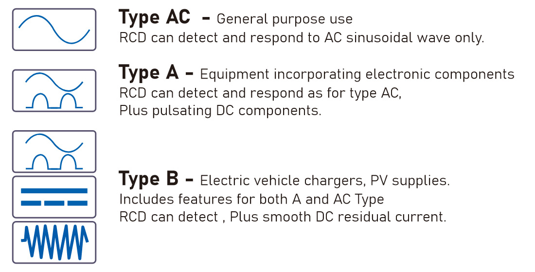
THE MAIN DIFFERENCE BETWEEN TYPE A AND TYPE AC
| Form | Residual Current and Current Waveform That Can Trip | Trip Current Range | |
| Type AC | AC Residual Current | 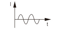 |
0.5 I△– I△n |
| Type A | AC Residual Current |  |
0.5 I△– I△n |
| Pulsating DC Residual Current | 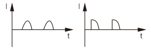 |
0.35~1.4I△n(or 2I△n )(Current lag Angle 0°) 0.25~1.4I△n(or 2I△n )(Current lag Angle 90°) 0.11~1.4I△n(or 2I△n )(Current lag Angle 135°) |
|
| Current stacking 6mA Smooth DC Residual Current | 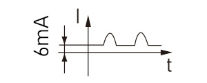 |
1.4I△n(or 2I△n) + 6mA | |
| RCD | Examples of type of equipment / load |
| Type AC | Resistive, Capacitive, Inductive loads generally without any electronic components, typically: · Immersion heater · Oven/Hob with resistive heating elements · Electric shower · Tungsten & halogen lighting |
| Type A | Single phase with electronic components. typically: · Single phase invertors · Class 1 IT and Multimedia equipment · Power supplies for Class 2 equipment · Appliances such as a washing machine that is not frequency controlled e.g. d.c. or universal motor · Lighting controls such as a dimmer switch and home and building electronic systems LED drivers · Induction hobs · Electric Vehicle charging where any smooth DC fault current is less than 6 mA Type A is also suitable for Type AC applications. |
| Type B | Three phase electronic equipment typically: · Inverters for speed control · UPS · Electric Vehicle charging where any smooth DC fault current is greater than 6mA · Photo voltaic · Power Electronic Converter Systems (PECS) typically: · Industrial machines · Cranes Type B is also suitable for Type AC and Type A applications. |
DETECT WAVEFORM TYPE AND CLASSIFICATION
| Definition of Residual Current Waveform | Waveform | Leakage Circuit Breaker Type | Tripping Range | |||
| Type AC | Type A | Type B | ||||
 |
 |
 |
Tripping Current | Tripping Time | ||
| Sinusoidal Exchange |  |
✓ | ✓ | ✓ | 0.5~1 IΔn | 1 IΔn: t≤0.3s 2 IΔn: t≤0.15s 5 IΔn: t≤0.04s |
| Pulsating Half Wave |  |
✕ | ✓ | ✓ | 0.5~1.4 IΔn | |
| Pulsating Half Wave + Direct Current (6mA) |  |
✕ | ✓ | ✓ | Max 1.4 IΔn | |
| Pulsating Half Wave + Direct Current (10mA) |  |
✕ | ✕ | ✓ | Max 1.4 IΔn | |
| High Frequency (up to 1KHz) |
 |
✕ | ✕ | ✓ | 150Ηz, 0.5~2.4 IΔn |
|
| ✕ | ✕ | ✓ | 400Hz, 0.5~6 IΔn |
|||
| ✕ | ✕ | ✓ | 1000Hz, 1~14 IΔn |
|||
| Two Phase rectified full wave |  |
✕ | ✕ | ✓ | 0.5~2 IΔn | 2 IΔn: t≤0.3s 4 IΔn: t≤0.15s 10 IΔn: t≤0.04s |
| Three Phase rectified full wave |  |
✕ | ✕ | ✓ | 0.5~2 IΔn | |
| Direct Current |  |
✕ | ✕ | ✓ | 0.5~2 IΔn | |
Outline And Installation Dimensions
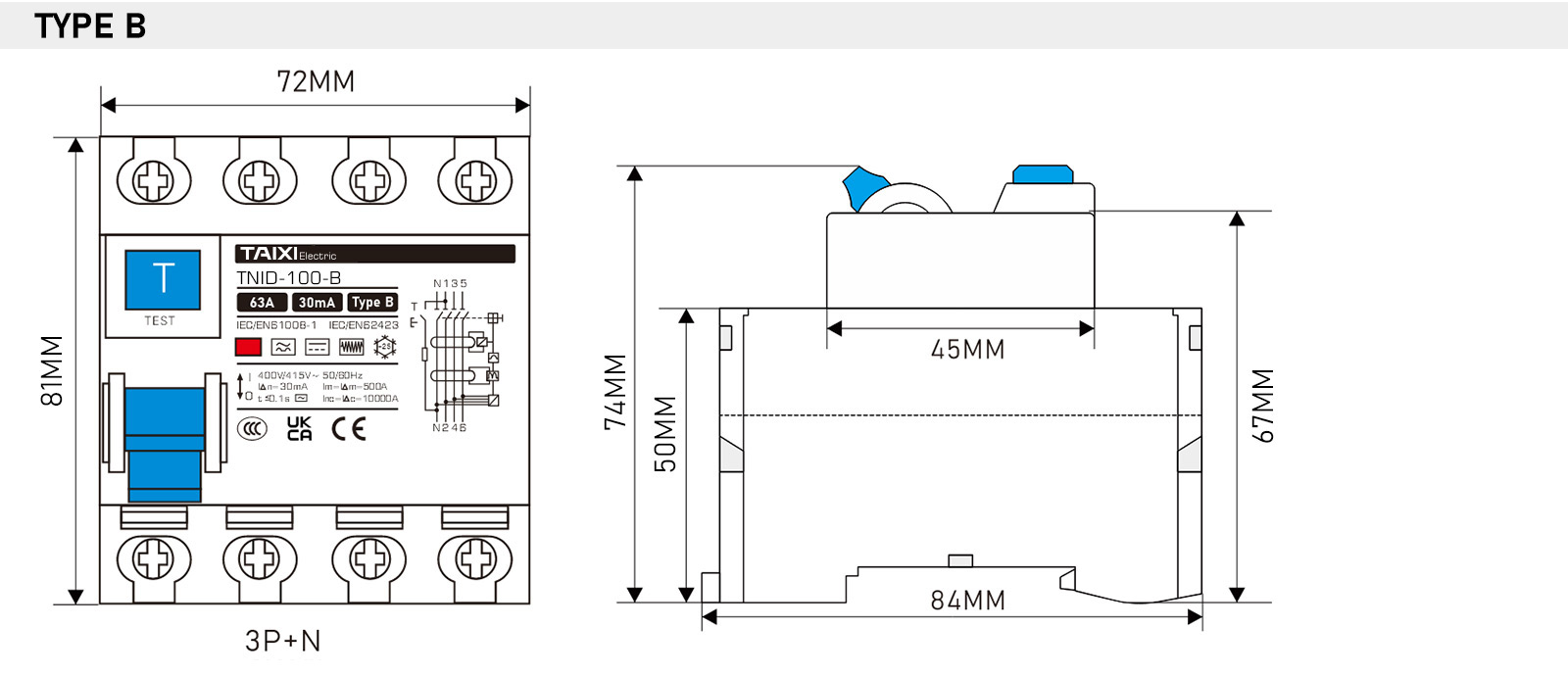
view and download
| File name(Click to view) | File type | file size | View times | Click to download |
Product related news
| News title | Promulgator | Release time | View times | Click to read |


