


Parameters
Details
Size&weight
Related
Video
Message
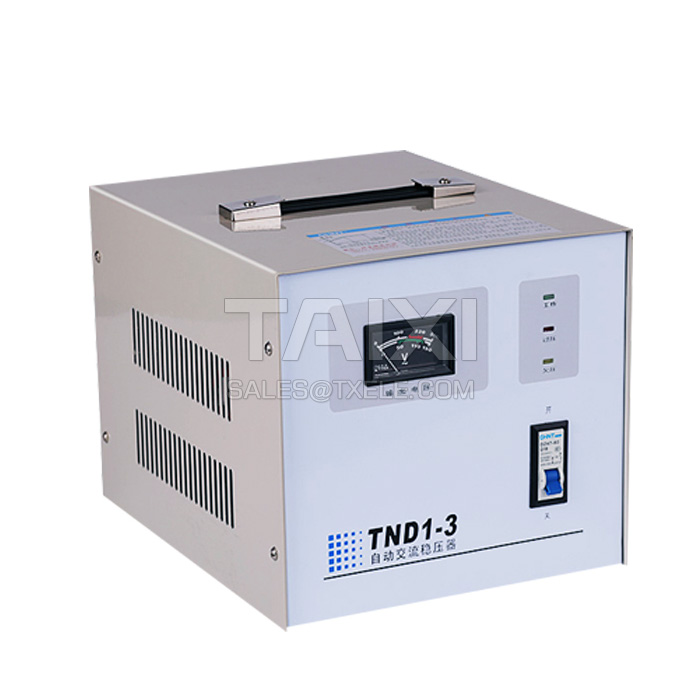
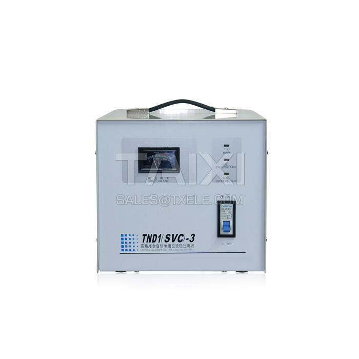
Product Overview
SVC Voltage Stabilizer (TND Single Phase Voltage Stabilizer, TNS three phase voltage stabilizer) is composed of contact regulator and auto control circuit. Sampling the voltage signal, amplifying and then controlling the servo motor to drive the arm and the brush to rotate in the desired direction, so that the output voltage is adjusted to the rated value to achieve voltage regulation. Performance indicators fully comply with the Q/ZT78 standard.
SVC Voltage Stabilizer has the advantages of beautiful appearance, small size, light weight, low power consumption, various protection functions, stability and reliability, and small output waveform distortion. Can be widely used in industrial production, scientific research, medical and health, household appliances and other areas with large voltage fluctuation of power grid or large changes in the grid voltage, can provide high-quality power to any load.
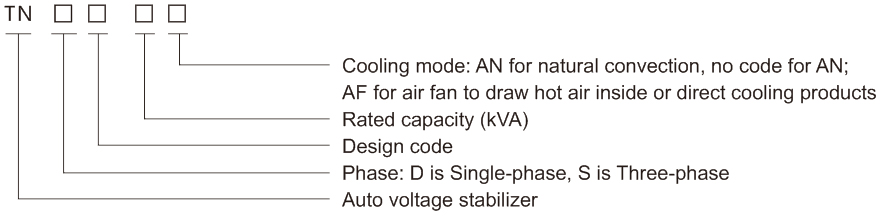
Model and Meaning
Normal working conditions and installation conditions
SVC Voltage Stabilizer Ambient temperature: -5°C~+40°C.
SVC Voltage Stabilizer Relative humidity: no more than 90% (at +20°C).
SVC Voltage Stabilizer Altitude: not exceed 2000m.
SVC Voltage Stabilizer Installation: The installation environment should be well-ventilated, without obvious pollution, corrosive gas, dust, combustibles, and combustible gas.
SVC Voltage Stabilizer Relative humidity: no more than 90% (at +20°C).
SVC Voltage Stabilizer Altitude: not exceed 2000m.
SVC Voltage Stabilizer Installation: The installation environment should be well-ventilated, without obvious pollution, corrosive gas, dust, combustibles, and combustible gas.
Main parameters and technical performance
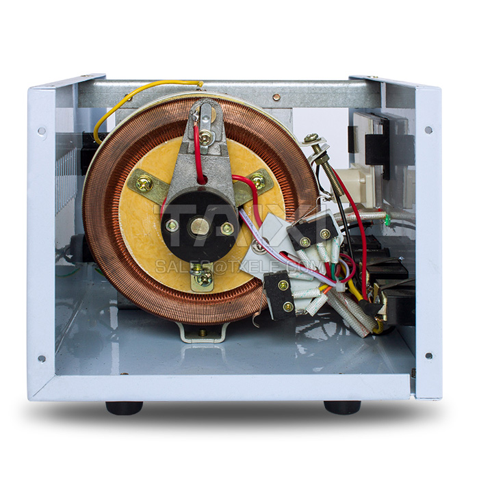
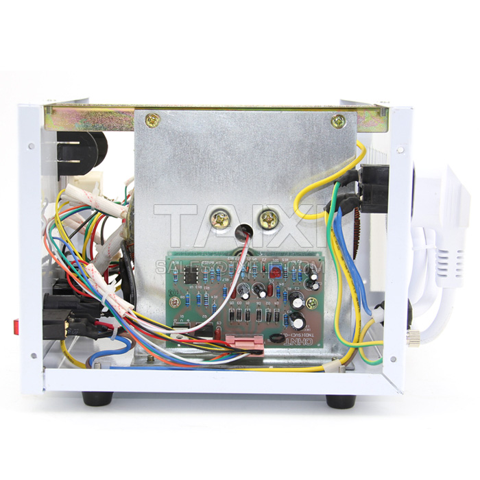
Structure Feature
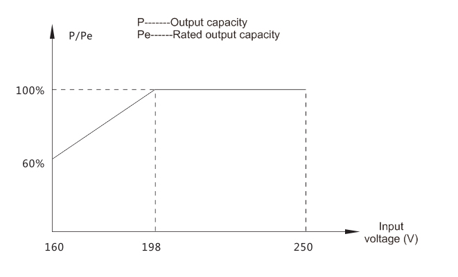
The output capacity of the SVC Voltage Stabilizer is closely related to the input voltage value. The output capacity curve is shown in the figure. When the input phase voltage is lower than 198V (three-phase wire voltage is 342V), the rated output capacity will be reduced. When the output voltage is 110V, the output capacity is only 50% of the rated capacity (Characteristic curve is shown in Figure 1).
Outline and lnstallation Dimension
For your safety, please read the following selection requirements and precautions when ordering:
The input and output of three-phase products are three-phase four-wire system wiring, so the zero line must be connected when using.
When three-phase stabilized power supply is used for single-phase applications or three-phase applications, the max output per phase is one-third of the nominal capacity of the entire machine.
In case of selection, the stabilized power supply is reasonably selected according to the rated power, the starting surge current, the inductive or capacitive load of the electrical equipment. The output capacity should have sufficient allowance, especially when the impact load is selected, and the specific safety factor is shown in Table 3.
When the input voltage is lower than 198V, the output capacity will be reduced, so to reduce the load and derating use to avoid overload, the specific characteristics shown in Figure 1; when using 110V, 220V output or simultaneous use, the maximum total output current must not exceed the rated output current. When using 110V output, the max capacity is only half of the rated capacity. When the input voltage is lower than 198V, it should also be used in proportion to the curve in Figure 1 to avoid overload.

view and download
| File name(Click to view) | File type | file size | View times | Click to download |
Product related news
| News title | Promulgator | Release time | View times | Click to read |