


PVSPD DC Surge Protection Device
Surge Protection Device | SPD


Parameters
Details
Size&weight
Related
Video
Message
INTRODUCTION
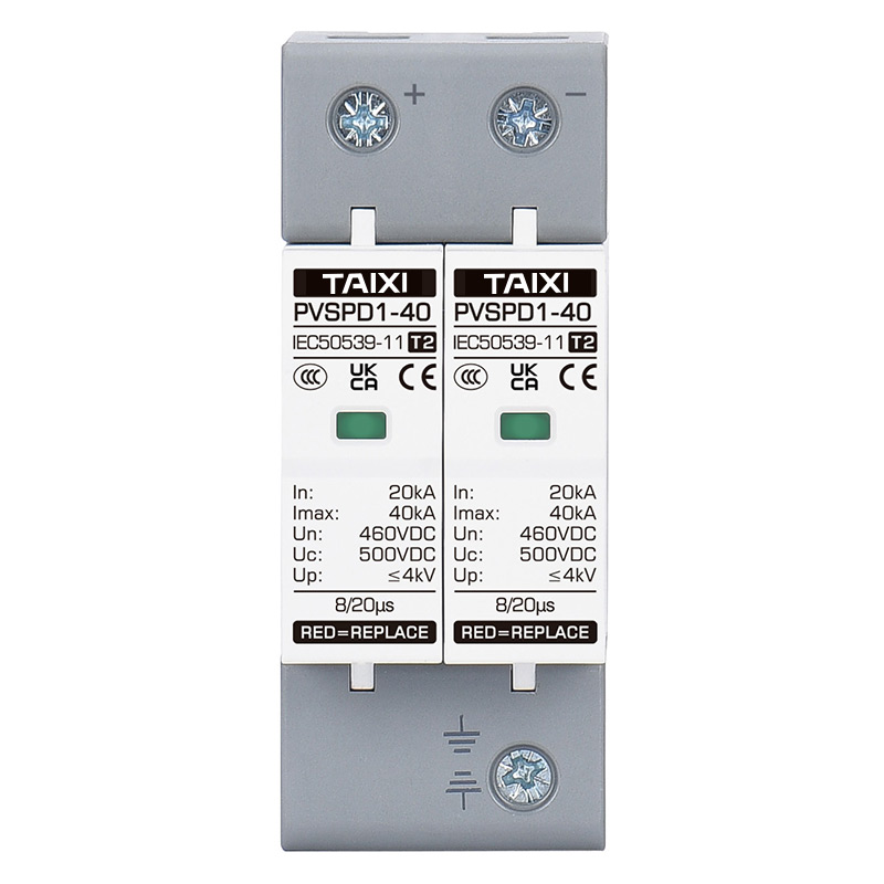
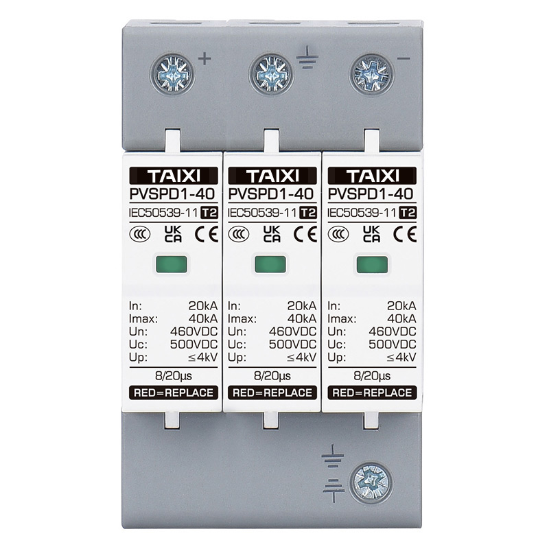
PVSPD DC surge protection device is applicable to the low-voltage standard IEC EN 50539-11, and is used to protect the DC system and other equipment from overvoltage and instantaneous overvoltage damage. When DC system experiences surge overvoltage due to lightning strikes or other reasons, the protector immediately conducts within nanosecond time, introducing surge overvoltage to the ground, thereby protecting the electrical equipment on the point network. DC surge protection device is a plug-in structure that can be quickly replaced after a module failure; After the lightning protection module fails, the color of the indicator window changes from green to red, and an alarm signal is sent to the remote alarm device connected to the remote signal terminal of the product.
DC Surge protection device are widely used in photovoltaic combiner boxes, power inverters, DC distribution cabinets, etc. It has the advantages of high discharge current, fast response time, and low residual voltage. The maximum photovoltaic voltage reaches UC≤1200VDC.
FEATURES
1. Voltage types: DC500V 690V 800V 1000V 1200V;
2. 8/20µs, T2 protection;
3. High discharge capacity, quick response, pluggable;
4. Double thermal disconnection devices, providing more reliable protection;
5. Visual window display, green means normal, Red means defect(need to change new module);
6. Remote terminal optional.
ELECTRICAL TECHNICAL PARAMETERS
| Model | PVSPD |
| Standard | IEC EN50539-11; GB18802.11 |
| Protection Grade | T2, Class II |
| Max Continuous Working Voltage Uc | 500V 690V 800V 1000V 1200V |
| Nominal Discharge Current In 8/20μs | 20KA |
| Max Discharge Current In 8/20μs | 40KA |
| Lightning Impulse Current 10/350μs | 12.5KA |
| Voltage Protection Level Up | ≤4KV |
| Number of Poles | 2P / 3P |
| Response Time Ta | ≤25ns |
| Connecting Cable | ≥4mm², Ground Wire ≥6mm² |
| Method of Installation | 35mm DIN Rail |
| Matched Fuse or Circuit Breaker | ≥32A |
| Operating Temperature Range | -40°C ~ +80°C |
| Housing Color Module/Base | Grey/White |
| Certificate | CE, ISO9001-2015 |
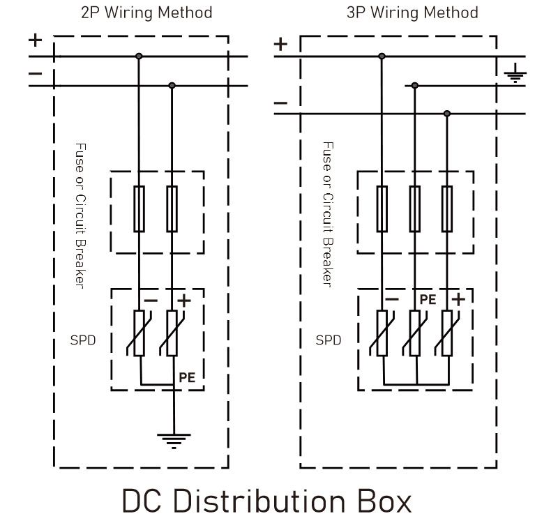
WIRING DIAGRAM
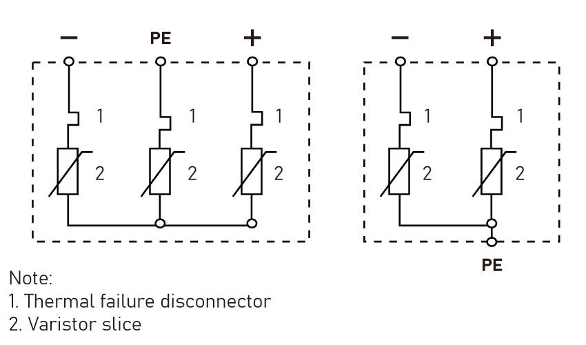
MAIN STRUCTURE AND WORKING PRINCIPLE
In the photovoltaic power generation system, protective devices are connected between the positive and negative poles of the line and the ground. Under normal circumstances, the protective device is in a high resistance state. When a surge overvoltage occurs in the power grid due to lightning strikes or other reasons, the protective device will immediately conduct in nanoseconds, introducing the surge overvoltage to the ground, thereby protecting the electrical equipment on the power grid. When the surge voltage passes through the protective device and disappears, the protective device will change back to a high resistance state, This will not affect the normal operation of the power grid. The electrical schematic diagram of the surge protector is shown in the following figure.
CHIP
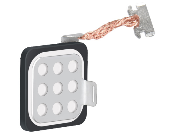
| Max Continuous Working Voltage Uc | Resistance Chip Size |
| 500VDC | 34MM*34MM*4.6MM |
| 690VDC | |
| 800VDC | |
| 1000VDC | |
| 1200VDC |
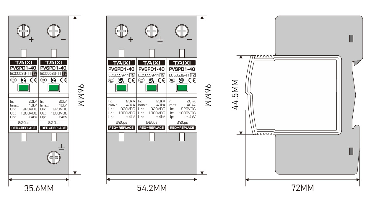
OUTLINE AND INSTALLATION DIMENSIONS

view and download
| File name(Click to view) | File type | file size | View times | Click to download |
Product related news
| News title | Promulgator | Release time | View times | Click to read |