


Parameters
Details
Size&weight
Related
Video
Message
Scope of Application
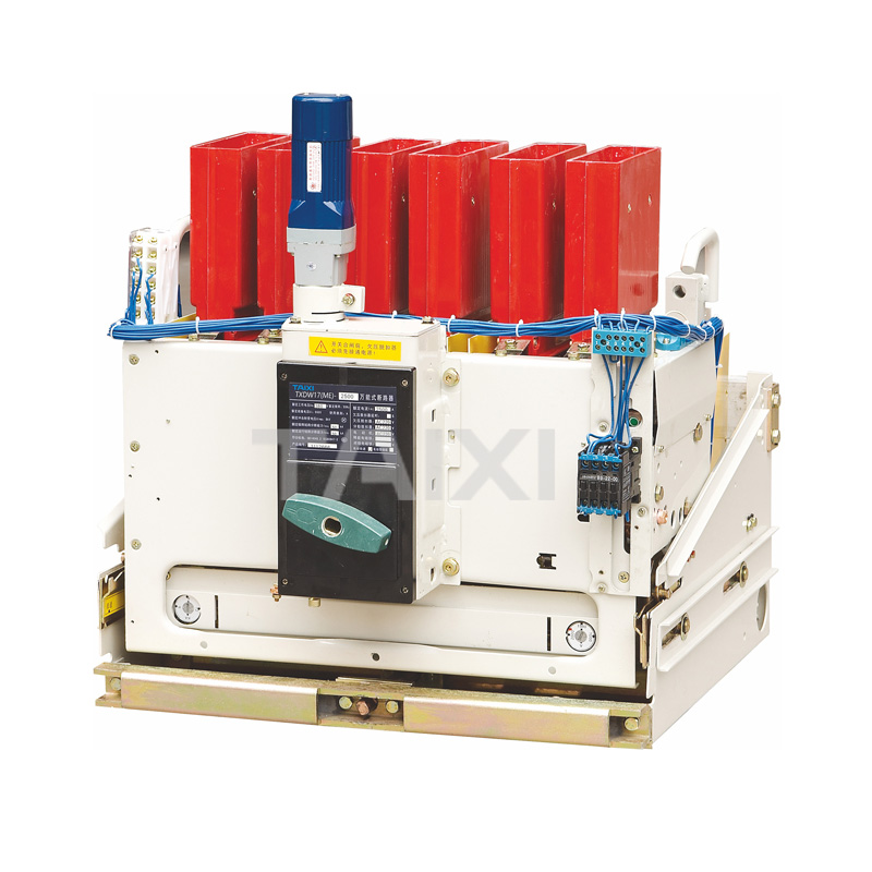
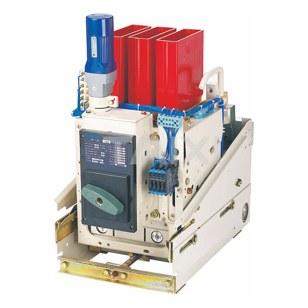
DW17 low voltage air circuit breaker (hereinafter referred to as air circuit breaker) is suitable for the distribution network of 50Hz, rated current up to 3900A and rated operational voltage 690V and below, to distribute power and protect overload and under voltage and short circuit of circuit and power equipment. Under normal conditions, it can be used for infrequent conversion of the line. This ACB Breaker complies with the GB14048.2.
Model and meaning

Normal working conditions and installation conditionsn
1. The ambient air temperature is -5°C~+40°C, the average value within 24h does not exceed +35°C.
2. Installation location: The altitude does not exceed 2000m.
3. Atmospheric conditions: Atmospheric relative humidity does not exceed 50% when the ambient air temperature is +40°C; the relative humidity can be higher at lower temperatures; and the maximum relative humidity of the wettest month is 90%. At the same time, the average minimum temperature for the month is +25°C, and special measures should be taken for the occasional condensation caused by temperature changes.
4. Pollution grade: Level 3.
5. Installation conditions: The low voltage air circuit breaker shall be installed in a complete set or in a separate installation according to the instructions, and the inclination to the vertical surface shall not exceed 5°.
Main technical data and performance
2. Breaking capacity of the circuit breaker
The making and breaking capacity of this series low voltage air circuit breaker is required by O-3min→CO-3min→CO. When the power supply is the upper or lower line, the index of the breaking capacity is the same, and the specific index is shown in Table 2.
Note: Manually direct operated low voltage air circuit breaker should not be used in circuits with a expected peak current exceeding 10kA.
3. The power consumption of shunt release, undervoltage release, blocking electromagnet, energy release
electromagnet and operating motor are shown in Table 3. Note: 1. The operation voltage range of the shunt release is 70%~110% of the rated operational voltage.
2. The operation voltage of undervoltage release, blocking electromagnet, motor operating mechanism and energy release device is 85%~110% of the rated operational voltage.
4. Protection characteristics of overcurrent release
4.1 The long delay operation of the overload release is shown in Table 4
Note: The three-phase low voltage air circuit breaker allows the operating current to increase by 10% in the two-phase load and the single-phase load to increase by 20%.
4.2 The operating current range of the short-circuit release is ±20% of the setting value
5. The mechanical life and the electric life of the low voltage air circuit breaker are shown in Table 5
Note: 1. When DW17-1900 pre-store energy for the motor, its mechanical life is 10000 times.
2. The test conditions for the electrical life are: u=1.05 Ue, I=Ie, COSΦ=0.8±01.
6. The making and breaking capacity of the auxiliary switch is shown in Table 6.
Its mechanical life is 20,000 times and its electric life is 10,000 times. 7. Safety distance between low voltage air circuit breaker (including arc distance) is shown in Table 7.
Note: 1. All live parts and grounded parts must be reliably insulated.
2. This table is for AC 380V data.
8. The rated current adjustment range of the low voltage air circuit breaker over-current release and the weight of the low voltage air circuit breaker are shown in Table 8.

9. The types and specifications of low voltage air circuit breaker are shown in Table 9.

The making and breaking capacity of this series low voltage air circuit breaker is required by O-3min→CO-3min→CO. When the power supply is the upper or lower line, the index of the breaking capacity is the same, and the specific index is shown in Table 2.
Note: Manually direct operated low voltage air circuit breaker should not be used in circuits with a expected peak current exceeding 10kA.
3. The power consumption of shunt release, undervoltage release, blocking electromagnet, energy release
electromagnet and operating motor are shown in Table 3. Note: 1. The operation voltage range of the shunt release is 70%~110% of the rated operational voltage.
2. The operation voltage of undervoltage release, blocking electromagnet, motor operating mechanism and energy release device is 85%~110% of the rated operational voltage.
4. Protection characteristics of overcurrent release
4.1 The long delay operation of the overload release is shown in Table 4
Note: The three-phase low voltage air circuit breaker allows the operating current to increase by 10% in the two-phase load and the single-phase load to increase by 20%.
4.2 The operating current range of the short-circuit release is ±20% of the setting value
5. The mechanical life and the electric life of the low voltage air circuit breaker are shown in Table 5
Note: 1. When DW17-1900 pre-store energy for the motor, its mechanical life is 10000 times.
2. The test conditions for the electrical life are: u=1.05 Ue, I=Ie, COSΦ=0.8±01.
6. The making and breaking capacity of the auxiliary switch is shown in Table 6.
Its mechanical life is 20,000 times and its electric life is 10,000 times. 7. Safety distance between low voltage air circuit breaker (including arc distance) is shown in Table 7.
Note: 1. All live parts and grounded parts must be reliably insulated.
2. This table is for AC 380V data.
8. The rated current adjustment range of the low voltage air circuit breaker over-current release and the weight of the low voltage air circuit breaker are shown in Table 8.
9. The types and specifications of low voltage air circuit breaker are shown in Table 9.
Installation and maintenance
1. Before the installation, check the insulation resistance of the circuit breaker with a 500V megohmmeter. It should be not less than 10MΩ when the temperature of the surrounding medium is 20 and the relative humidity is 50%~70%. Otherwise, it should be processed and can be used only when the insulation resistance meets the requirement.
2. Check the specifications of the circuit breaker before installation.
3. During the process of closing and opening for the circuit breaker, the movable part and the arc extinguishing chamber shall be free from jamming and rubbing. And the indicating sign can correctly indicate the working status of the circuit breaker.
4. When the fixed circuit breaker is installed, its base should be in a vertical horizontal position and fixed with mounting screws. At the same time, it must be grounded reliably and the ground screw is marked with a symbol.
5. Installation should consider the installation spacing of the circuit breaker (see Table 7).
6. The installation of the circuit breaker must be smooth.
7. Check whether the shunt release and the undervoltage release action is normal, then under the undervoltage release pull-up conditions, manual operation or electric operation should be reliable to close the low voltage air circuit breaker, when using shunt release, undervoltage release to trip or manual tripping, the circuit breaker shall be reliably disconnected and five operation tests shall be conducted.
8. When there is specific noise from the iron core during use, the anti-rust oil on the work surface should be wiped clean.
9. low voltage air circuit breaker should be regularly maintained:
a. Clean up the dust to keep the low voltage air circuit breaker well insulated;
b. Lubricate each rotating or sliding part;
c. Check the setting values and operating values of various releases and the operation process;
d. Check the contact system: Wipe off the smoke marks on the contacts and the small metal particles on the contact surfaces should be removed. If the thickness of the contact alloy is as small as 1mm, the contacts must be replaced; If the main contact overtravel is less than 4mm and the static and dynamic arc contact is just in contact, the relevant contact must be adjusted when the distance between the dynamic and static main contacts is less than 2mm; check whether the soft joint has damage, if there is a fracture layer, remove the layer, or find the fracture seriously, it should be replaced.
e. After the low voltage air circuit breaker is subjected to a short-circuit current, in addition to the need to check the contact system, the smoke marks on both sides of the arc-quench cover must be cleaned. If the arc-extinguishing grid burns seriously, the arc-extinguishing cover should be replaced.
f. Connect the busbars of the main circuit terminal of the low voltage air circuit breaker and fix them with insulation at 200~250mm from the terminals to avoid damage caused by electric power.
Outline and lnstallation Dimensions
1. Outline and installation dimension of DW17-800, 1000, 1250, 1600, 1900 3P fixed low voltage air circuit breaker
Figure 1. Horizontal wiring

Figure 2. Vertical wiring (Note: Install insulation plate Y)

2. Installation dimension of DW17-630, 800, 1000, 1250, 1600, 1900 3P fixed circuit breaker (mm)
3. Outline and installation dimension of DW17-2000, 2500, 2900 3P fixed low voltage air circuit breaker are shown in Figure 3, 4
Figure 3. Horizontal wiring

Figure 4. Vertical wiring (Note: Install insulation plate Y)

4. Outline and installation dimension of DW17-3200, 3900 3P fixed low voltage air circuit breaker are shown in Figure 5, Figure 6
Figure 5. Horizontal wiring

Figure 6. Vertical wiring (Note: Install insulation plate Y)

5. Outline and installation dimension of DW17-630, 800, 1000, 1250, 1600 3P drawer low voltage air circuit breaker are shown in Figure 7
Figure 7: 1) Center line of operating mechanism. 2) Safety spacing A, B, C and D refer to fixed form. 3) Pull distance of switch

6. Outline and installation dimension of DW17-1900 3P drawer low voltage air circuit breaker are shown in Figure 8
Figure 8: 1) Center line of operating mechanism. 2) Safety spacing A, B, C and D refer to fixed form. 3) Pull distance of switch

7. Outline and installation dimension of DW17-2000, 2500 3P drawer low voltage air circuit breaker are shown in Figure 9
Figure 9: 1) Center line of operating mechanism. 2) Safety spacing A, B, C and D refer to fixed form. 3) Pull distance of switch

8. Outline and installation dimension of DW17-2900 3P drawer circuit breaker are shown in Figure 10
Figure 10: 1) Center line of operating mechanism. 2) Safety spacing A, B, C and D refer to fixed form. 3) Pull distance of switch

9. Outline and installation dimension of DW17-3200 3P drawer air circuit breaker are shown in Figure 11
Figure 11: 1) Center line of operating mechanism. 2) Safety spacing A, B, C and D refer to fixed form. 3) Pull distance of switch

10. Outline and installation dimension of DW17-3900 3P drawer low voltage air circuit breaker are shown in Figure 12
Figure 12: 1) Center line of operating mechanism. 2) Safety spacing A, B, C and D refer to fixed form. 3) Pull distance of switch

11. Outline and installation dimension of DW17-630~1900 4P fixed air circuit breaker are shown in Figure 13, 14
Figure 13, 14: 1) Center line of operating mechanism. 2) Safety spacing A, B, C and D refer to fixed form. 3) Pull distance of switch
Horizontal wiring

Installation dimension of DW17-630~1900 4P fixed air circuit breaker
Vertical wiring (Note: Install insulation plate Y)

12. Outline and installation dimension of DW17-2000, 2500 3P drawer low voltage air circuit breaker are shown in Figure 15, 16
Figure 15, 16: 1) Center line of operating mechanism. 2) Safety spacing A, B, C, D refer to fixed form. 3) Pull distance of switch
Horizontal wiring

Vertical wiring (Note: Install insulation plate Y)


view and download
| File name(Click to view) | File type | file size | View times | Click to download |
Product related news
| News title | Promulgator | Release time | View times | Click to read |