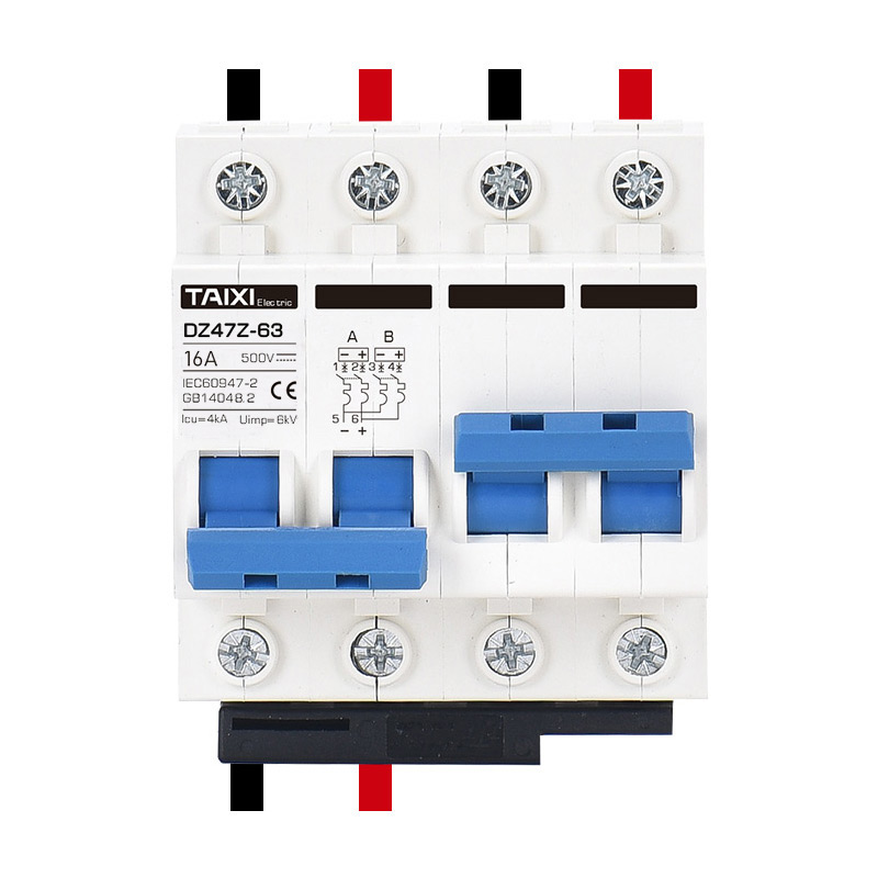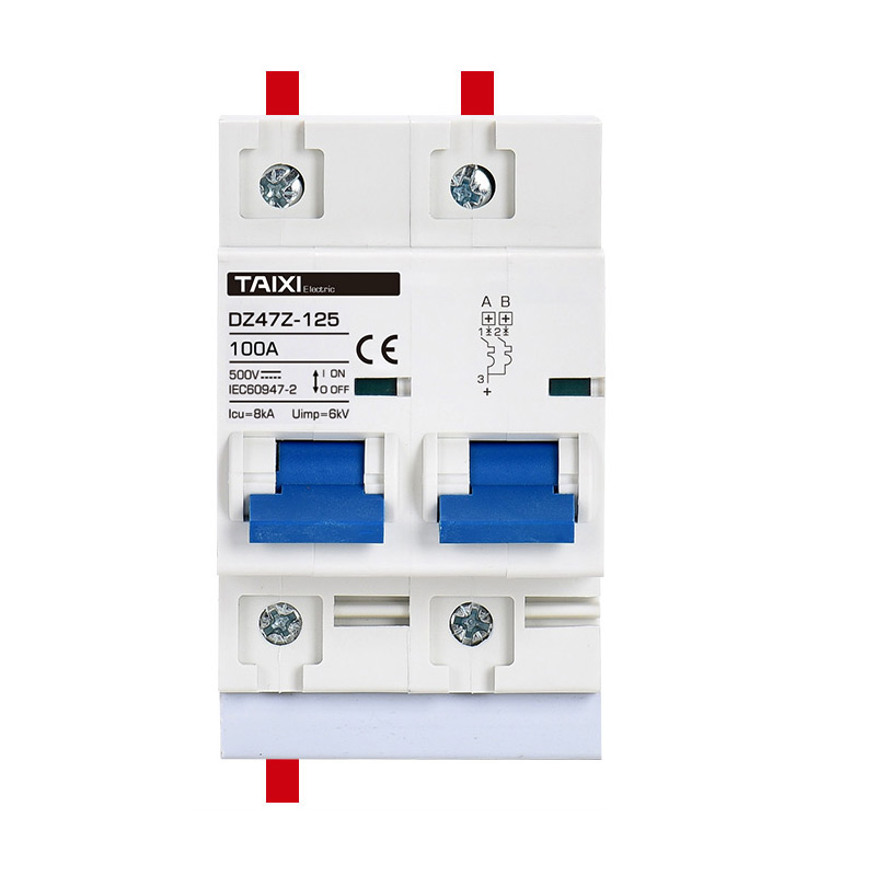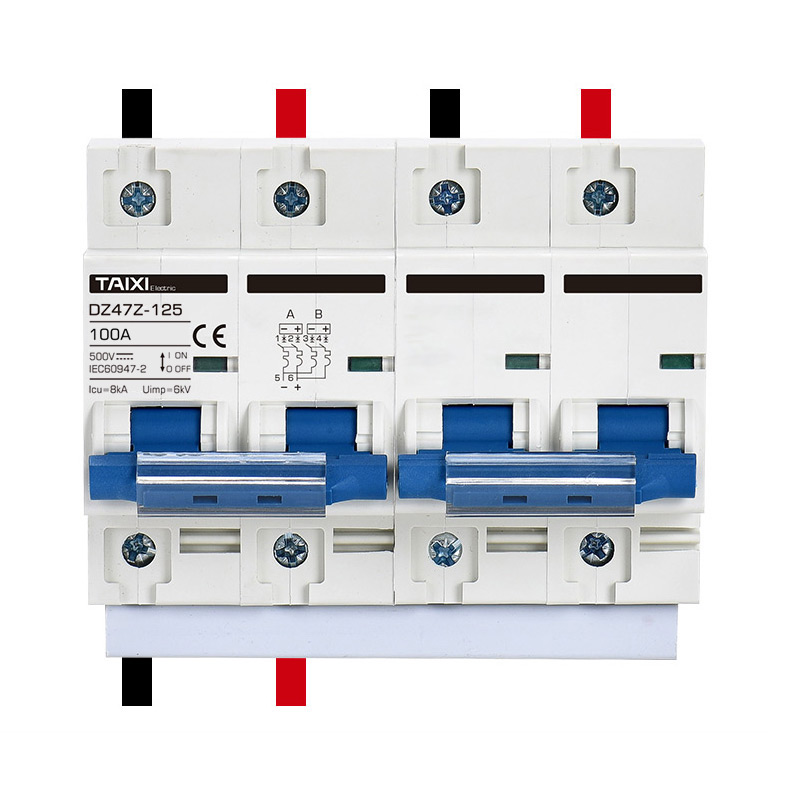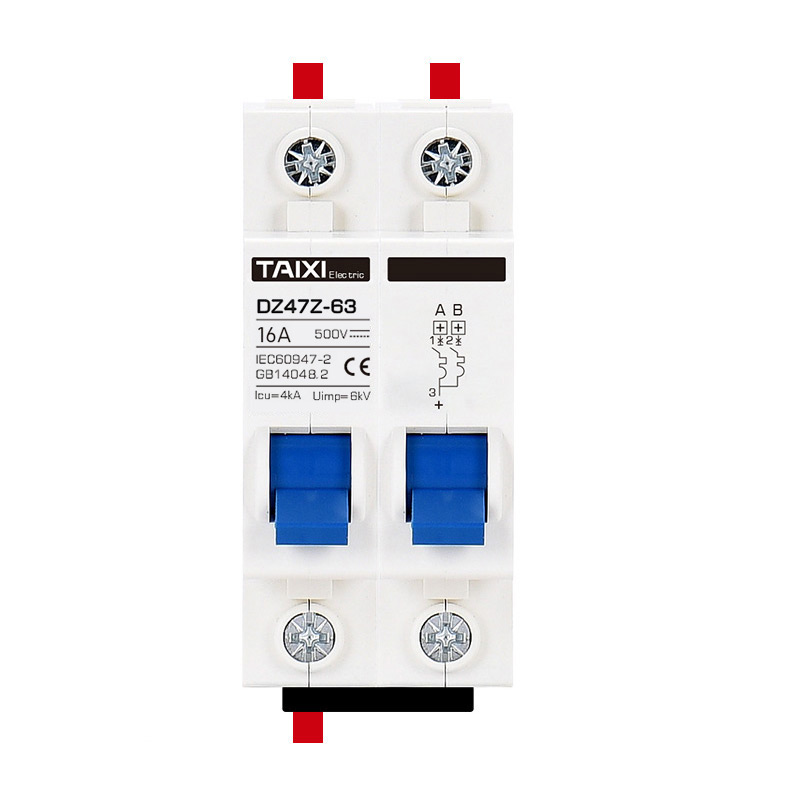


DZ47ZSD Manual Transfer Switch
Transfer Switch
![]()
Parameters
Details
Size&weight
Related
Video
Message
SCOPE OF APPLICATION
DZ47Z photovoltaic DC circuit breakers are suitable for circuit with rated current below 125A and rated DC voltage of 1000V. For infrequent conversions. The product has beautiful appearance, standard rail installation, and has on-off display. The terminals have wiring functions up and down. Be sure to pay attention to the polarity of "﹢/﹣" when wiring. It is used for three-pole circuit breakers in 750V circuits, and the balance positive circuit is connected in series with two poles. The circuit breaker can also be equipped with accessories such as auxiliary contacts, alarm contacts and shunt release, which are widely used in communications, batteries, locomotives and other industries.
DC circuit breakers comply with IEC60947-2-1997, GB14048.2-200.1 standards
| Poles | 1P | 2P | 3P | 3P |
| Breaking Capacity | 4.5kA | 4.5kA | 4.5kA | 4.5kA |
| Withstand Voltage | 250V | 500V | 750V | 1000V |
| Wiring Diagram |  |
 |
 |
 |
| Remarks: (1) L+ positive pole of power supply, L- negative pole of power supply; (2) + positive pole of circuit breaker, - negative pole of circuit breaker; (3) loade quipment | ||||
THE MAIN TECHNICAL PARAMETERS
| Rated Current | 1,2,4,6,10,16,20,25,32,40,50,63,80,100,125A |
| Frame Class | 1-63A/63-125A |
| Poles | 1P,2P,3P,4P |
| Rated Working Voltage | DC 12V~400V or AC 90V~400V |
| Rated Impulse Withstand Voltage(1.2/50) Uimp | 6kV |
| Rated Short-circuit Breaking Capacity | 4.5kV |
| Current Limiting Level | 3 |
| Electrical Life | 1000 |
| Mechanical Life | 10000 |
| Installation | 35MM DIN Rail Mount or M3 Screw Side Mount |
| Ambient Temperature | -30°C~+70°C |
| Heat And Humidity Resistance | Class 2 (at 55°C, relative humidity 95%) |
| Installation | TH35-7.5 DIN Rail |
| Protection Class | IP20 |
| Standards Compliant | IEC60898-2/GB10963.2 |
| Terminal Connection Type | Phillips Screws |
| Adapter Cable | 6-63A 1-25mm² 16-3AWG | 80-125A 8-35mm² 16-2AWG |
| Tightening Torque | 3.0N.M |
| Certificate | CCC、CE |
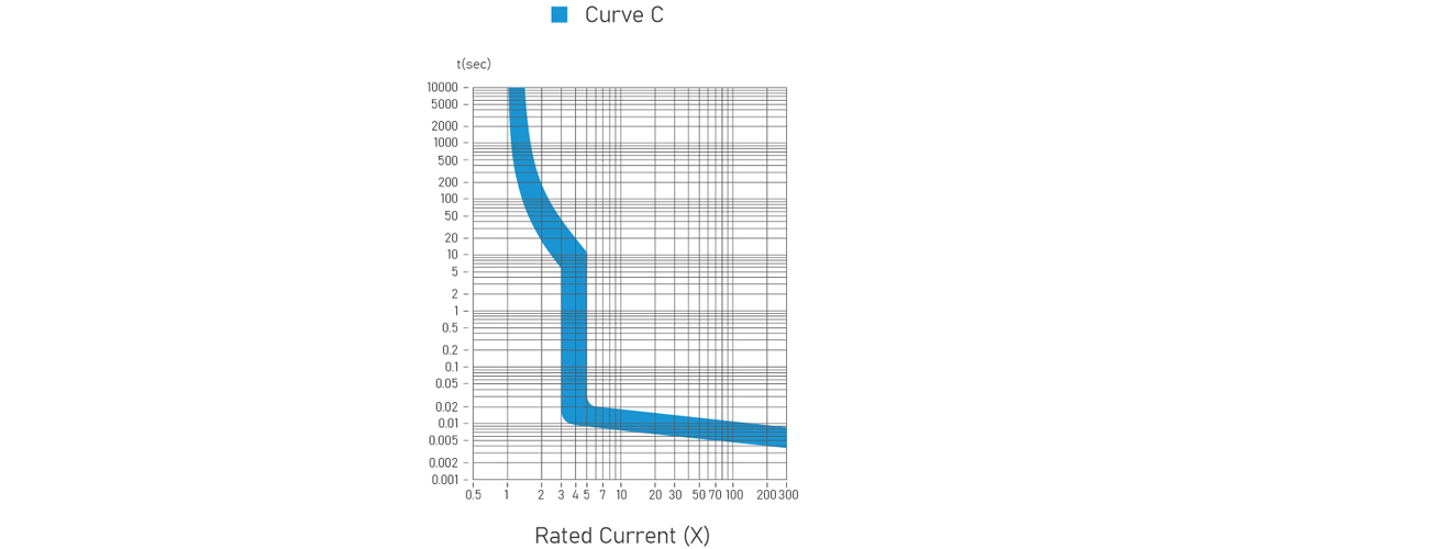
| Thermo - Magnetic Release Characteristic | B-Curve (3-5In) |
| Combination With Accessories Auxillary Contact | |
| Auxillary Contact | Yes |
| Alarm Contact | Yes |
| Shunt Release | Yes |
| Under Voltage Release | Yes |
According to the type of instantaneous release
| Tripping curve | AC Instantaneous tripping range | DC Instantaneous tripping range |
| B | 3In≤I≤5In | 4.4In≤I≤6.6In |
| C | 4In<I≤10In | 6.8In<I≤10.2In |
RATED SHORT-CIRCUIT BREAKING CAPACITY
| Rated current | Poles | Rated Voltage | Short circuit current |
| 1-125A | 1 | 220V | 3000A |
| 2-4 | 4500A |
MECHANICAL AND ELECTRICAL LIFE
| Type | Frequency | Operation frequency (times) | Rated current (A) |
| Electrical life | 1000 | 240 | 1-32 |
| 120 | 40-125 | ||
| Mechanical life | 10000 | 240 | 1-125 |
OVERCURRENT PROTECTION CHARACTERISTICS (REFERENCE TEMPERATURE 30℃)
| No. | Curve | Current (A) | Starting state | DC | Times | Result |
| a | B、C | 1~63 | Cold | 1.13In | t≤1h | No-trip |
| b | B、C | 1~63 | Immediately after the preceding item | 1.45ln | t≤1h | Trip |
| c | Curve | In≤32A | Cold | 2.55ln | 1s<t<60s | Trip |
| In>32A | 1s<t<120s | |||||
| d | B | 1~63 | Cold | 4ln | 0.1s≤t≤45s(In≤32A) 0.1s≤t≤90s(In≤32A) |
Trip |
| C | 7ln | 0.1s≤t≤15s(In≤32A) 0.1s≤t≤30s(In≤32A) |
||||
| e | B | 1~63 | Cold | 7In | t<0.1s | Trip |
| C | 15In |
POWER CONSUMPTION POLE OF CIRCUIT BREAKER
| Rated current In(A) | Maximum power consumption pole (W) |
| 1-10 | 2 |
| 16-32 | 3.5 |
| 40-63 | 5 |
| 80-125 | 8-10 |
CURRENT CORRECTION FACTORS USED AT DIFFERENT ALTITUDES
| Tripping curve | Rated current | Current correction index | Example |
| ≤2000m (2000~3000)m≥3000m | |||
| B、C | 1,2,4,6,10,15,20,25 32,40,50,63 80,100,125 |
1 0.9 0.8 | Rated current 20A products inUsage amount after derating at 3000 metersThe constant current is: 0.8x20=16A |
Wiring: It is suitable for wire connection of 25mm² and below. The wiring method is to press the connection with screws, and the torque is 2.5N·m.
| Rated current ln(A) | Copper wire cross-sectional area (mm2) |
| 1-6 | 1 |
| 10 | 1.5 |
| 16、20 | 2.5 |
| 25 | 4 |
| 32 | 6 |
| 40、50 | 10 |
| 63、80 | 16 |
| 100 | 25 |
| 125 | 35 |
| Temperature(℃) corrected current value(A) Rated current(A) |
-25 | -20 | -10 | 0 | 10 | 20 | 30 | 40 | 50 | 60 |
| 10 | 12.5 | 12.4 | 11.9 | 11.3 | 10.8 | 10.4 | 10 | 9.7 | 9.2 | 8.5 |
| 16 | 20 | 19.8 | 18.9 | 18.1 | 17.3 | 16.5 | 16 | 15.5 | 14.6 | 13.8 |
| 20 | 25 | 24.8 | 23.6 | 22.6 | 21.1 | 20.6 | 20 | 19.4 | 18.2 | 17.2 |
| 25 | 31.25 | 31 | 29.5 | 28.3 | 27 | 25.8 | 25 | 24.3 | 22.8 | 21.3 |
| 32 | 40 | 39.7 | 37.8 | 36.2 | 34.6 | 33 | 32 | 31 | 28.8 | 27.2 |
| 40 | 50 | 49.6 | 47.2 | 45.2 | 43.2 | 40.8 | 40 | 38.4 | 37.2 | 35.2 |
| 50 | 63.5 | 62.5 | 59 | 56.5 | 54 | 51.5 | 50 | 48 | 45.5 | 43 |
| 63 | 80.01 | 78.8 | 74.3 | 71.2 | 68 | 64.9 | 63 | 60.5 | 57.2 | 54.2 |
| 80 | 100 | 95.4 | 90 | 86 | 84 | 82 | 80 | 74 | 70 | 65 |
| 100 | 120 | 114.2 | 112 | 110 | 106 | 103 | 100 | 94 | 88 | 80 |
| 125 | 150 | 140 | 138 | 135 | 130 | 127 | 125 | 115 | 105 | 90 |
TEMPERATURE COMPENSATION
When the ambient temperature is not a benchmark of 30 degrees , the reference correction factor is as folows .
| Ambient Temperature | -20℃ | -10℃ | 0℃ | 10℃ | 20℃ | 30℃ | 40℃ | 50℃ | 60℃ |
| Current Correction Coefficient | 1.25 | 1.2 | 1.15 | 1.10 | 1.05 | 1.00 | 0.95 | 0.90 | 0.85 |
TRIPPING CHARACTERISTIC CURVE -- B TYPE
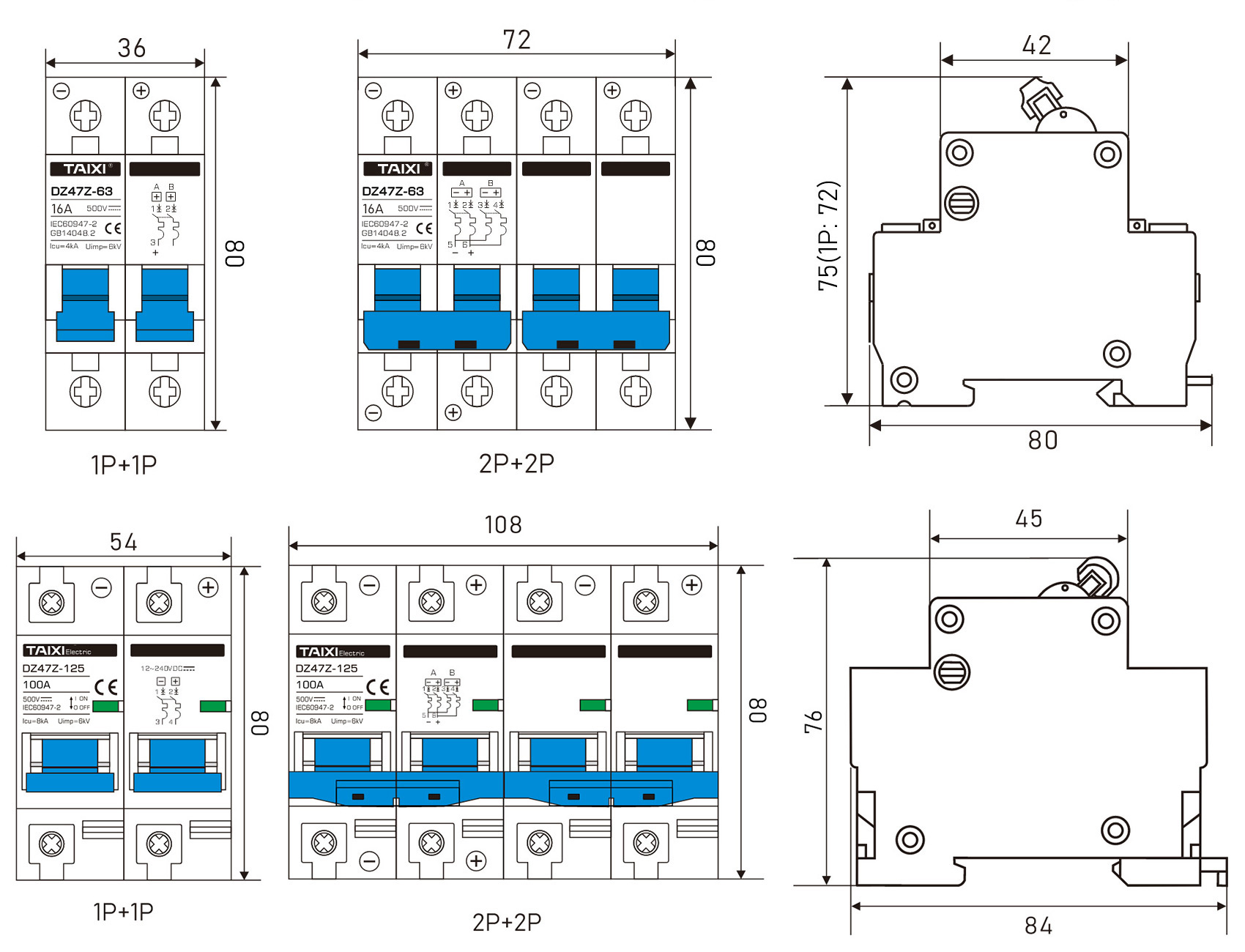
OUTLINE AND INSTALLATION DIMENSIONS
view and download
| File name(Click to view) | File type | file size | View times | Click to download |
Product related news
| News title | Promulgator | Release time | View times | Click to read |


