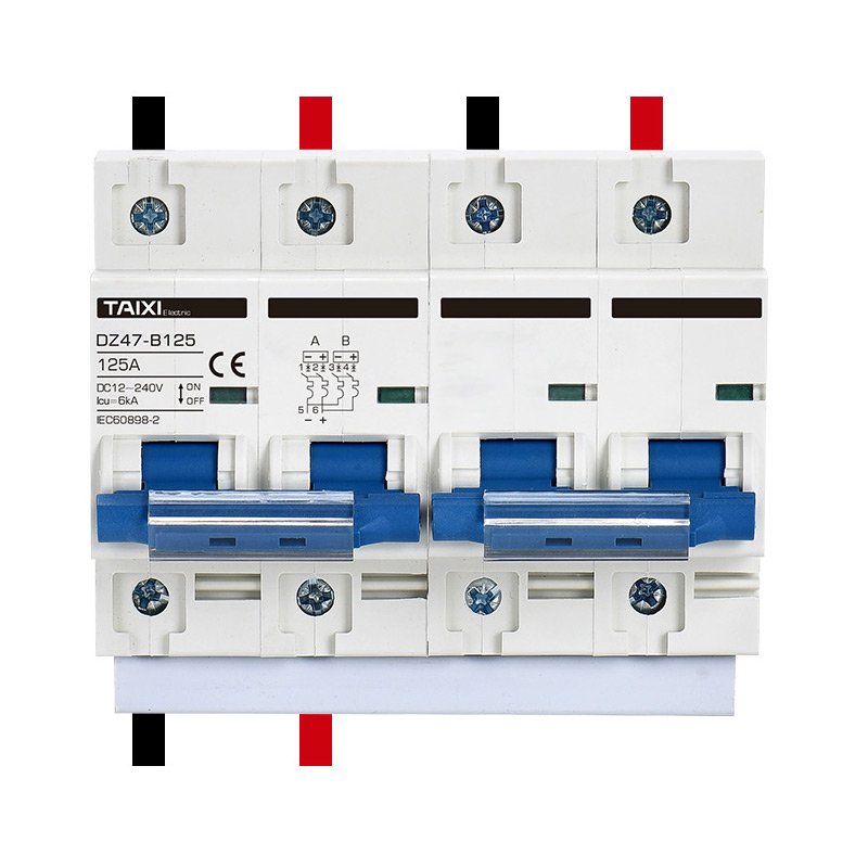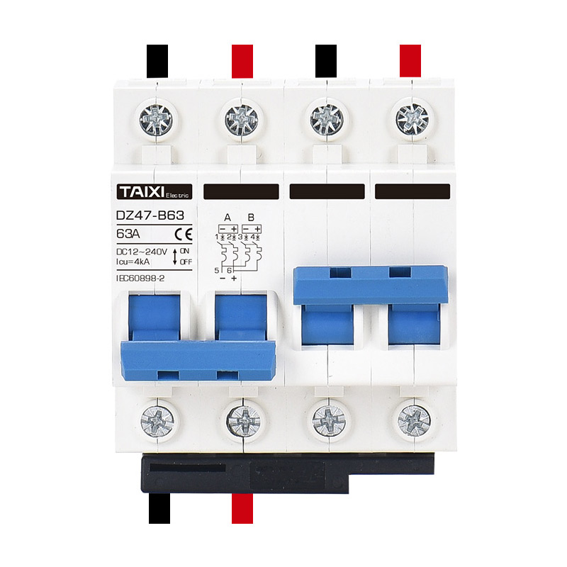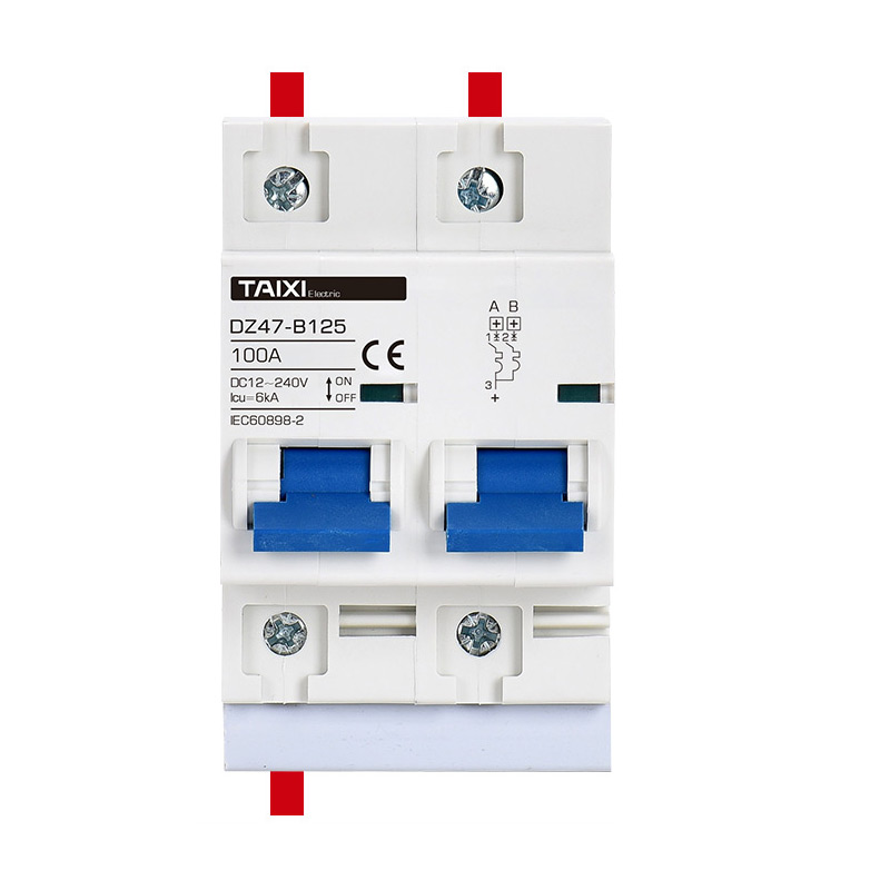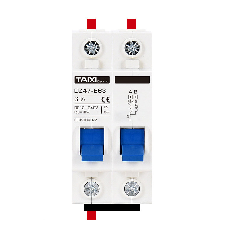


DZ47BSD Manual Transfer Switch
Transfer Switch
![]()
Parameters
Details
Size&weight
Related
Video
Message
SCOPE OF APPLICATION
DZ47BSD Manual Transfer Switch is a new product specially developed for low-voltage batteries such as photovoltaic solar UPS. DZ47B battery circuit breaker supports overload protection between 12-240V and short-circuit protection between 36-240V. The battery circuit breaker adopts B-curve (3-5ln) tripping capability, sensitive to tripping; battery circuit breaker has 1P+1P to switch 2 positive power supplies or 2 negative power supplies (switching standby Power supply and common power supply), 2P+2P to switch 2 battery switches (switching standby power supply and common power supply), four specifications; the minimum current of the battery switch can be 1A, and the maximum current can reach 150A.
NORMAL OPERATING CONDITIONS AND INSTALLATION CONDITIONS
The upper limit of ambient temperature does not exceed +40 °C, the lower limit does not less than -5°C, and the average temperature of 24h does not exceed +35 °C.
Altitude of the installation site should not exceed 2000m.
Atmospheric relative humidity at ambient air temperature +40°C is not more than 50%, it allowed to have a higher relative humidity at lower temperatures; for example at + 20°C up to 90%. Special precautions should be taken for condensation that may occasionally occur on the product due to temperature changes.
Pollution Degree: Grade 2.
Installation conditions: Installed in a place without significant impact, vibration, non-hazardous (explosive) medium.
Installation: TH35-7.5 installation rail.
Installation category: Class II, III.
TECHNICAL PARAMETERS
| Electrical Features | |
| Rated Current | 1-150A |
| Poles | 1P+1P, 2P+2P |
| Rated Voltage Ue | DC12-240V |
| Insulation Volage Ui | 500V |
| Rated Frequency | 50/60Hz |
| Rated Breaking Capacity | 2000A |
| Rated Impulse Withstand Voltage Uimp | 3kV |
| Dielectric Test Voltage At And Ind. Freq. For 1min | 1kV |
| Thermo-Magnetic Release Characteristic | B (3In ~ 6In) |
| Electrical Life | 4000 |
| Mechanical Life | 20000 |
| High Operating VoltageHigh Breaking Capacity | |
| Contact Position Indicator | YES |
| Protection Class | IP20 |
| Reference Temperature For Setting Of Thermal Element | 30°C |
| Ambient Temperature(With Daily Average ≤35°C) | -5°C~40°C |
| Storage Temperature | -25°C~+70°C |
| Terminal Connection Type | Phillips Screws |
| Suitable For Cable Cross-Section | 6-63A 1.5-25MM²;80-150A 4-35MM² |
| Tightening Torque | 2.5-3.0N.m |
| Mounting | 35MM DIN Rail or M4 Side Mounted |
TRIPPING CHARACTERISTIC CURVE
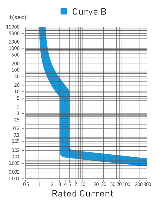
Rated short-circuit breaking capacity of DZ47B
| Trip Type | Rated Current | Rated short-circuit breaking capacity | COSΦ |
| B | 1A≤In≤40A | 6000A | 0.65~0.70 |
| B | 40A<In≤63A | 4000A | 0.75~0.80 |
Over-current protection characteristics under the ambient temperature of 30 ℃~35℃
| NO. | Trip Type | Rated Current In | Test Current A | Appointed Time | Expected Result | Initial State |
| 1 | B | All values | 1.13In | t≤1h | Non tripping | Cold |
| 2 | B | All values | 1.45In | t<1h | Tripping | Immediately after the last test |
| 3 | B | ≤32 | 2.55In | s | Tripping | Cold |
| >32 | 1s | |||||
| 4 | B | All values | 2In | t≤0.1s | Non tripping | Cold |
| 3In | ||||||
| 5 | B | All values | 3In | t≤0.1s | Tripping | Cold |
| 6In |
Circuit breaker temperature compensation coefficient
| Rated Current In (A) |
The temperature compensation coefficient corresponding to different temperature | ||||||||
| -10℃ | 0℃ | 10℃ | 20℃ | 30℃ | 40℃ | 50℃ | 55℃ | 60℃ | |
| 1-6 | 1.20 | 1.14 | 1.09 | 1.05 | 1.00 | 0.96 | 0.80 | 0.75 | 0.70 |
| 10-32 | 1.18 | 1.12 | 1.08 | 1.04 | 1.00 | 0.96 | 0.92 | 0.88 | 0.84 |
| 40-63 | 1.16 | 1.12 | 1.07 | 1.03 | 1.00 | 0.97 | 0.87 | 0.83 | 0.80 |
The correction factor of the current used by the circuit breaker at different altitudes
| Trip Type | Rated Current | ≤2000m | 2000~3000m | ≥3000m |
| B | 1~150A | 1 | 0.9 | 0.8 |
Wiring:25mm² and below for wire connection, wiring method is screws to tighten the wiring, the torque is 2.0N.m.
| Rated current In (A) | Copper conductor nominal cross-sectional area (mm²) |
| 1-6 | 1 |
| 10 | 1.5 |
| 16-20 | 2.5 |
| 25 | 4 |
| 32 | 6 |
| 40-50 | 10 |
| 63-80 | 16 |
| 100 | 25 |
| 125 | 35 |
OUTLINE AND INSTALLATION DIMENSIONS
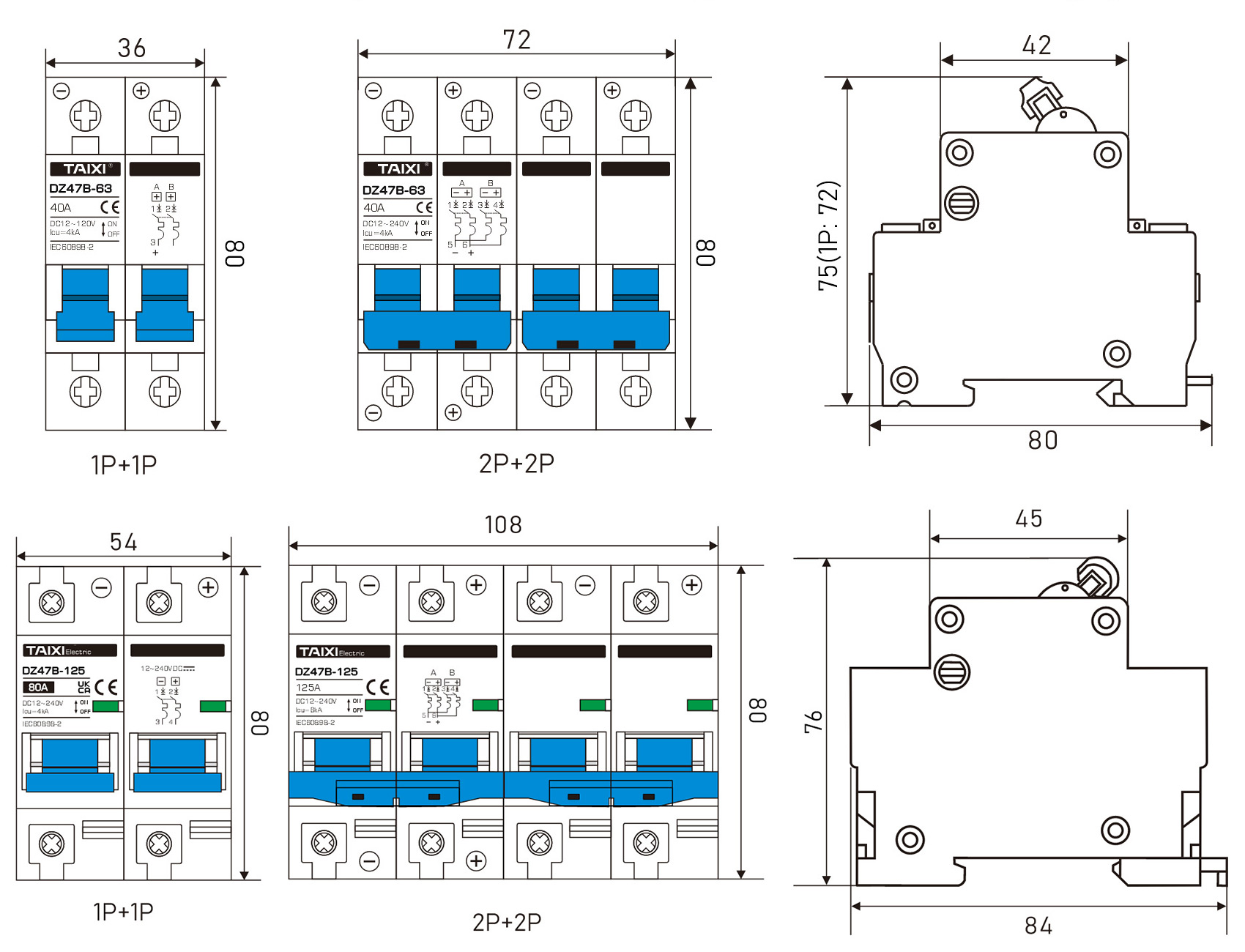
view and download
| File name(Click to view) | File type | file size | View times | Click to download |
Product related news
| News title | Promulgator | Release time | View times | Click to read |


