


TXM3Z DC Molded Case Circuit Breaker
Solar Disconnect Switch


Parameters
Details
Size&weight
Related
Video
Message
INTRODUCTION
TXM3Z DC molded case circuit breaker is an electrical device specially designed to protect DC circuits in photovoltaic energy storage systems. It plays a role in cutting off and protecting battery circuits in photovoltaic energy storage systems, ensuring the safe operation of the system and preventing circuit failures from causing fire and other hazards.
The maximum current of this DC circuit breaker can be reach 800A, and the maximum working voltage is 1500VDC. It has the characteristics of small size, high breaking capacity, short flashover, vibration resistance, and strong arc extinguishing ability, making it an ideal product for high-power battery energy storage systems. The design of this DC molded case circuit breakers takes into account the special needs of photovoltaic power generation and energy storage systems. It uses high-strength plastic shell materials, with good insulation performance and protective functions to adapt to outdoor environments and harsh weather conditions. In addition, it also has the characteristics of fast disconnection and action response to protect the photovoltaic energy storage system from overload, short circuit, and ground fault conditions.
The DC molded case circuit breaker is equipped with overload protection and short circuit protection functions. When the current in the photovoltaic energy storage system exceeds the rated value, overload protection will trigger the action of the circuit breaker to prevent circuit overload damage. When a short circuit fault occurs in the circuit, the short circuit protection will quickly cut off the current to prevent danger such as fire.
DC molded case circuit breakers have long service life and high reliability. It adopts high-quality materials and advanced manufacturing processes, with characteristics such as earthquake resistance, moisture resistance, and high temperature resistance, and is suitable for various harsh environmental conditions. At the same time, it also passes strict testing and certification to ensure its stable and reliable performance.
DC molded case circuit breaker is an electrical device used to protect DC circuits in photovoltaic energy storage systems. It has high strength plastic casing, overload and short circuit protection functions, long service life, and high reliability. It is suitable for high current environments in photovoltaic energy storage systems and can ensure the safe operation of the system and prevent hazards such as fires.
TXM3Z DC molded case circuit breakers are widely used in photovoltaic power generation and energy storage systems, wind power generation , as well as small energy storage cabinets/UPS and other high current applications.
Features
| High Operating Voltage | High Breaking Capacity | High Range Applications |
| High Voltage : DC1500V | TXM3Z 40kA | Working Temperature: -40°C~+70°C |
| Rated Working Voltage : DC1500V | ||
| Rated Ultimate Short-circuit Breaking Capacity (Icu) : 20kA | High Altitude To 5500m |
Meaning of Model Designation

| NAME | CONTENT |
| 1 Enterprise Code | TAIXI ELECTRIC CO.,LTD. |
| 2 Product Category | Moulded Case Circuit Breaker |
| 3 Design code | 3 |
| 4 Derived Code | Z : Direct-current |
| 5 Case Arade Rated Current | 125,320,800 |
| 6 Rated Voltage | DC1000V. DC1500V |
| 7 Rated Current | 63~800A |
CLASSIFICATION
| Classified By Operation Mode | Classified By Protection Form |
| 1. Directly operated by the noumenon |
1.Overload protection; 2.Short circuit protection; 3.Line isolation. |
ELECTRICAL TECHNICAL PARAMETERS
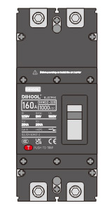
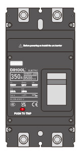
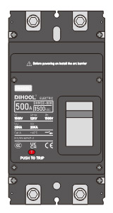
| Appearance |  |
 |
 |
 |
||
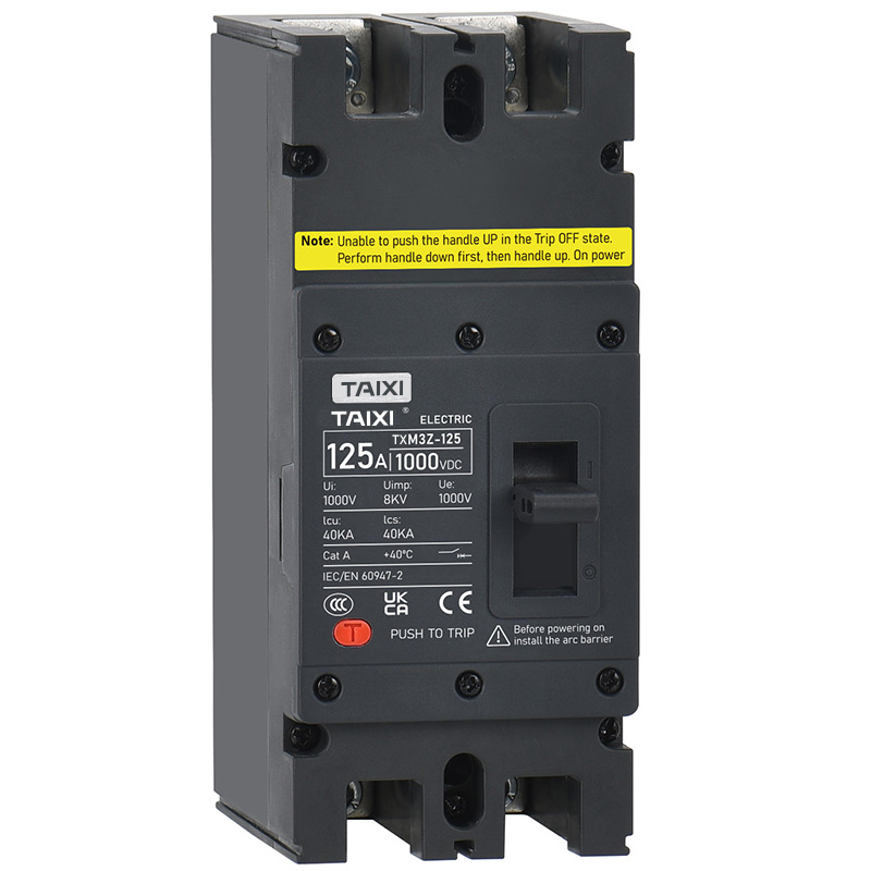
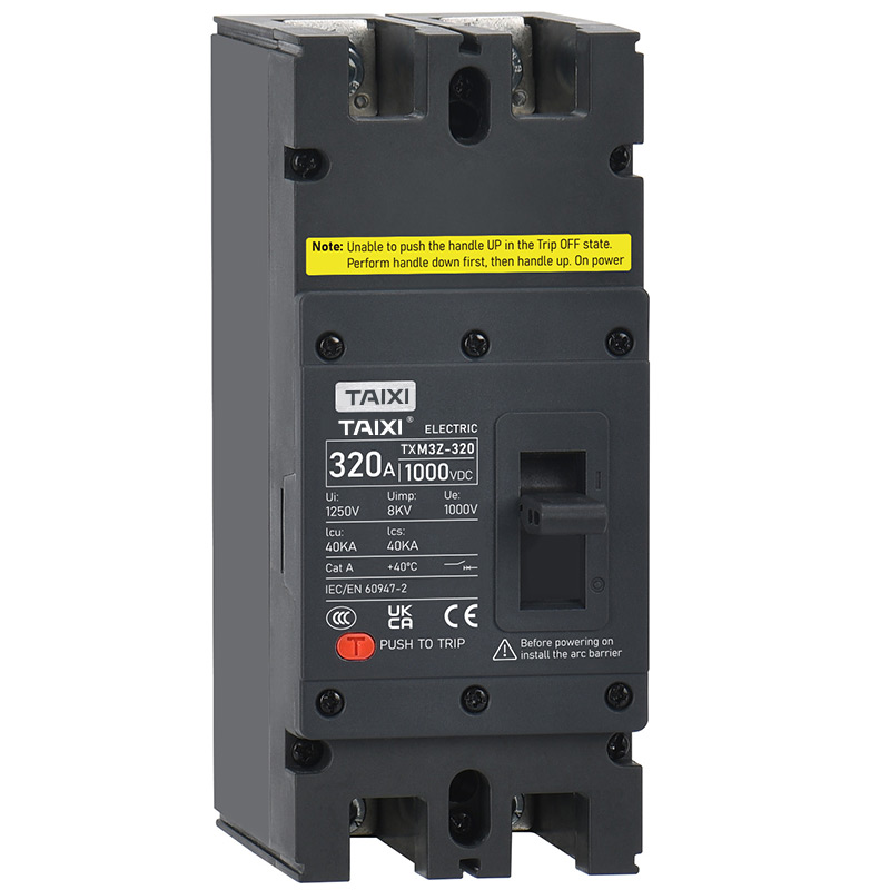
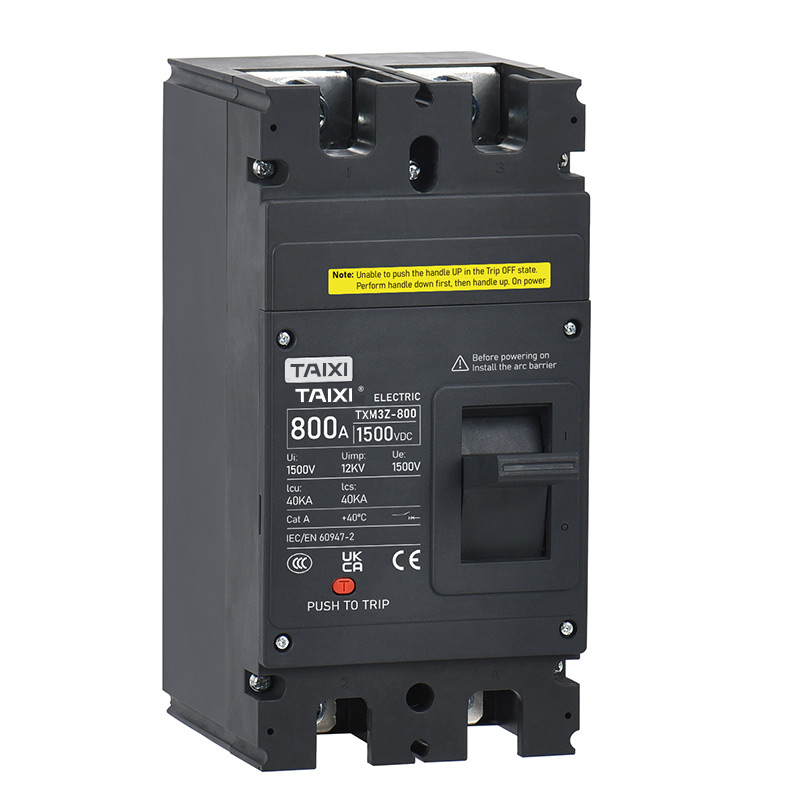
| Model | TXM3Z-125 | TXM3Z-320 | TXM3Z-400 | TXM3Z-800 | ||
| Poles | 2 | 2 | 2 | 2 | ||
| Rated Voltage Ue(V)DC | 1000 | 1000 | 1000 | 1500 | 1000 | 1500 |
| Insulation Voltage Ui(V) | 1000 | 1250 | 1500 | 1500 | ||
| Rated Impulse Withstand Voltage Uimp(kV) | 8 | 8 | 12 | 12 | ||
| Rated Current In(A) | 63,80,100,125 | 160,200,250,300,320 | 350,400 | 500,630,700,800 | ||
| Rated Operating Short-Circuit Breaking Capacity Icu(kA) | 20 | 20 | 40 | 20 | 40 | 20 |
| Rated Breaking Capacity Ics(kA) | lcs=100%Icu | |||||
| Connection | Up in and down out, down in and up out | |||||
| Use Category | A | |||||
| Isolation Function | Yes | |||||
| Ambient Temperature | -35°C ~ +70°C | |||||
| Mechanical Life | 20000 | 20000 | 10000 | 5000 | ||
| Electrical Life | 2000 | 2000 | 1000 | 700 | 1000 | 700 |
| Standards | IEC/EN 60947-2 , GB/T 14048.2 | |||||
| Accessories | Shunt Tripping Device, Auxiliary Contacts, Alarm Contacts, Motor-operated Drive,Hand Control Mechanism | |||||
| Certificates | CCC. CB. CE. TüVtututu | |||||
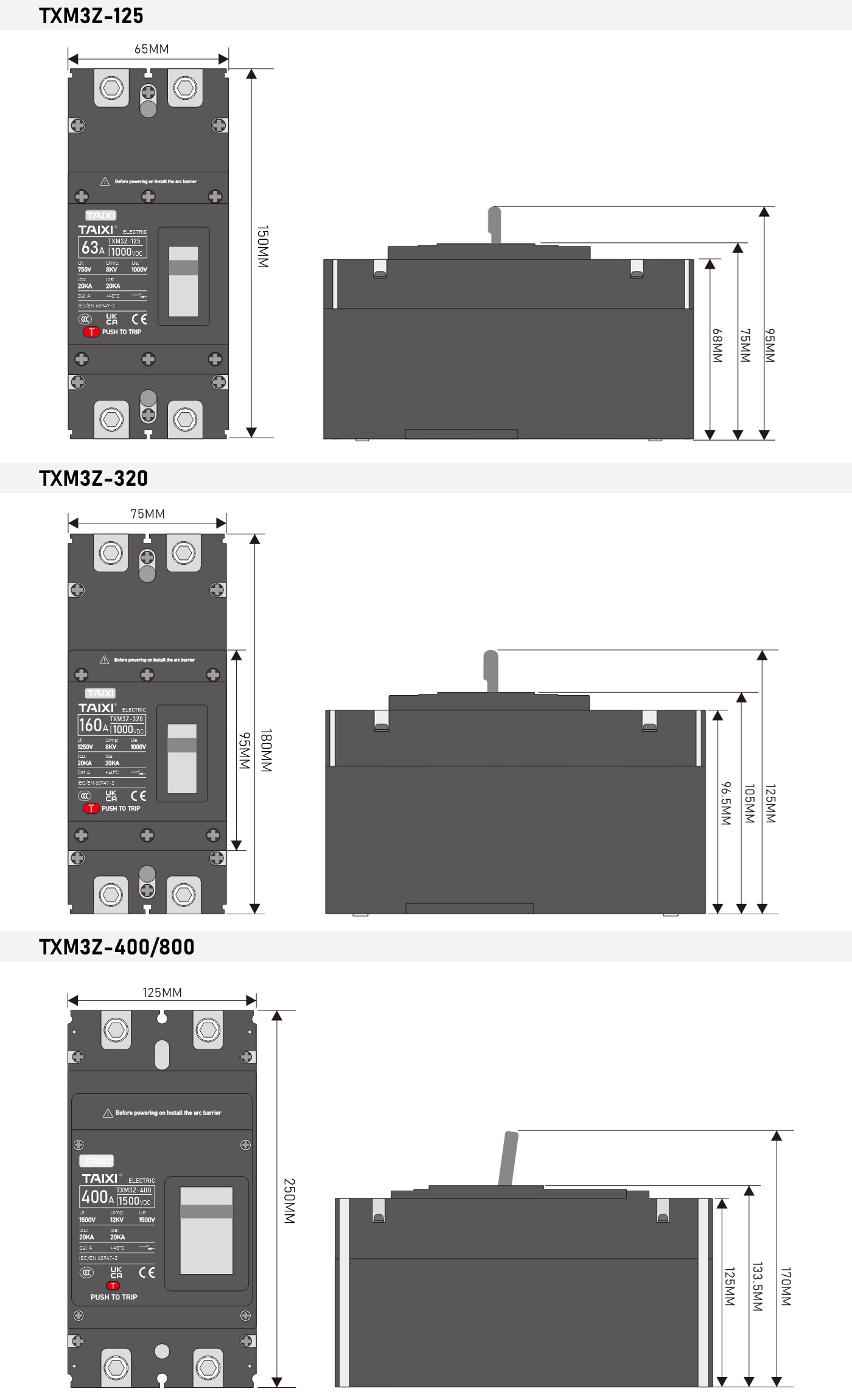
Dimensions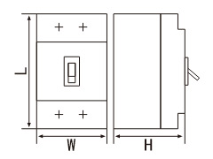 |
150x65x95(2P) (L×W×H) |
180x75x125(2P) (L×W×H) |
250x125x170(2P) (L×W×H) |
250x125x170(2P) (L×W×H) |
||
TEMPERATURE COMPENSATION COEFFICIENT
| Model | Current Correction Coefficient (In) | ||||||
| +40℃ | +45℃ | +50℃ | +55℃ | +60℃ | +65℃ | +70℃ | |
| TXM3Z-125 | 1.00 | 1.00 | 1.00 | 1.00 | 0.95 | 0.93 | 0.90 |
| TXM3Z-320 | 1.00 | 1.00 | 1.00 | 0.94 | 0.92 | 0.90 | 0.88 |
| TXM3Z-400 | 1.00 | 1.00 | 1.00 | 1.00 | 0.95 | 0.93 | 0.90 |
| TXM3Z-800 | 1.00 | 1.00 | 1.00 | 0.94 | 0.92 | 0.90 | 0.88 |
ALTITUDE COMPENSATION COEFFICIENT
| Model | Current Correction Coefficient (In) | ||||||
| 2000 Meters | 3000 Meters | 4000 Meters | 5000 Meters | ||||
| TXM3Z-125 | 1.00 | 1.00 | 1.00 | 0.96 | |||
| TXM3Z-320 | 1.00 | 0.97 | 0.94 | 0.90 | |||
| TXM3Z-400 | 1.00 | 1.00 | 1.00 | 0.96 | |||
| TXM3Z-800 | 1.00 | 0.97 | 0.94 | 0.90 | |||
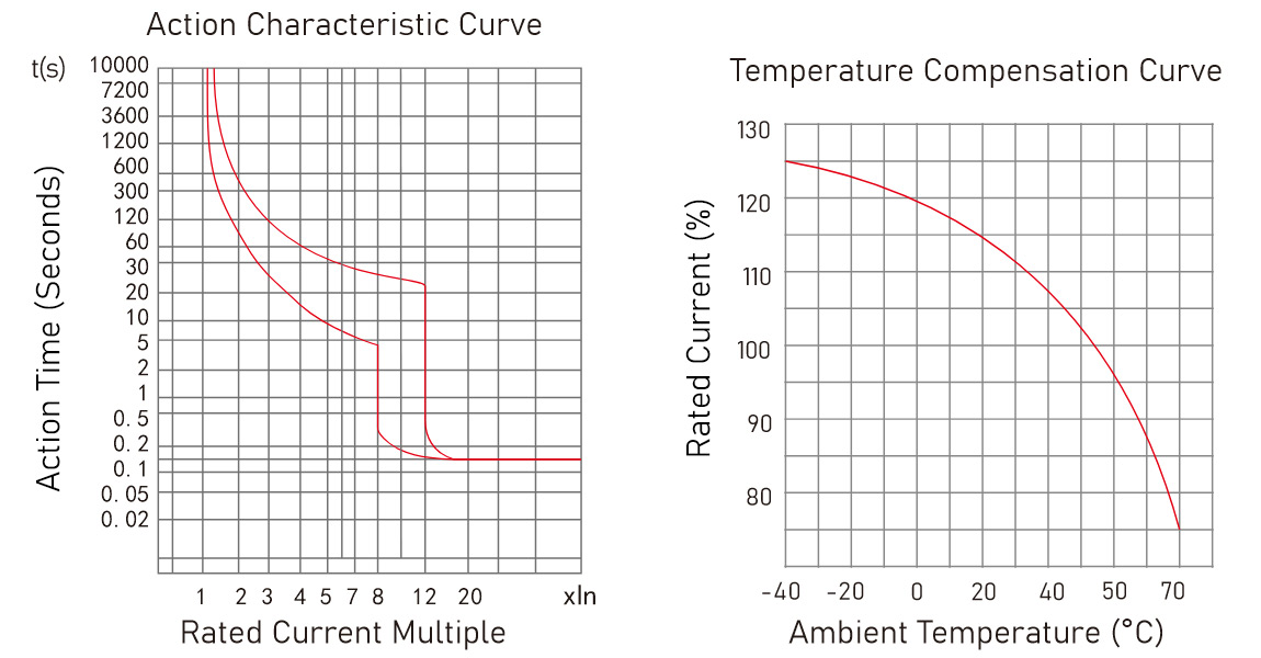
TRIPPING CHARACTERISTIC CURVE
RELEASE DEVICE AND ATTACHMENTS CODE

| Attachments Code | Attachments | TXM3Z-320 | TXM3Z-400/800 |
| 300 | No Internal Attachments | -- | -- |
| 3.8 | Alarm Contact | 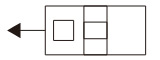 |
|
| 310 | Shunt Tripping Device |  |
|
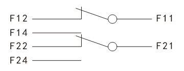
| 302 | Auxiliary Contact (2NO2NC) | -- |  |
AUXILIARY CONTACT (CURRENT PARAMETERS)
| Case Arade Rated Current | Conventional Thermal Current (Ith) | Conventional Thermal Current (Ith) |
| Inm < 250 | 3A | 0.30A |
| Inm > 400 | 6A | 0.40A |
AUXILIARY CONTACT (CURRENT PARAMETERS)
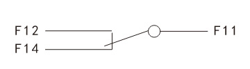
| When the circuit breaker is in the "open" position |
 |
 |
|
| When the circuit breaker is in the "close” position |
 |
 |
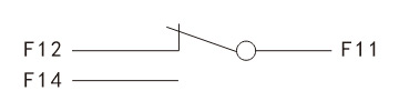
ALARM CONTACTS AND THEIR COMBINATIONS
| Alarm contacts(Ue=220V , Ith=3A) | |
| When the circuit breaker is in the "open" and "close" positions | 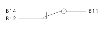 |
| When the circuit breaker is in the "trip-free” position | 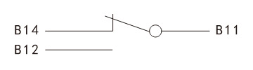 |
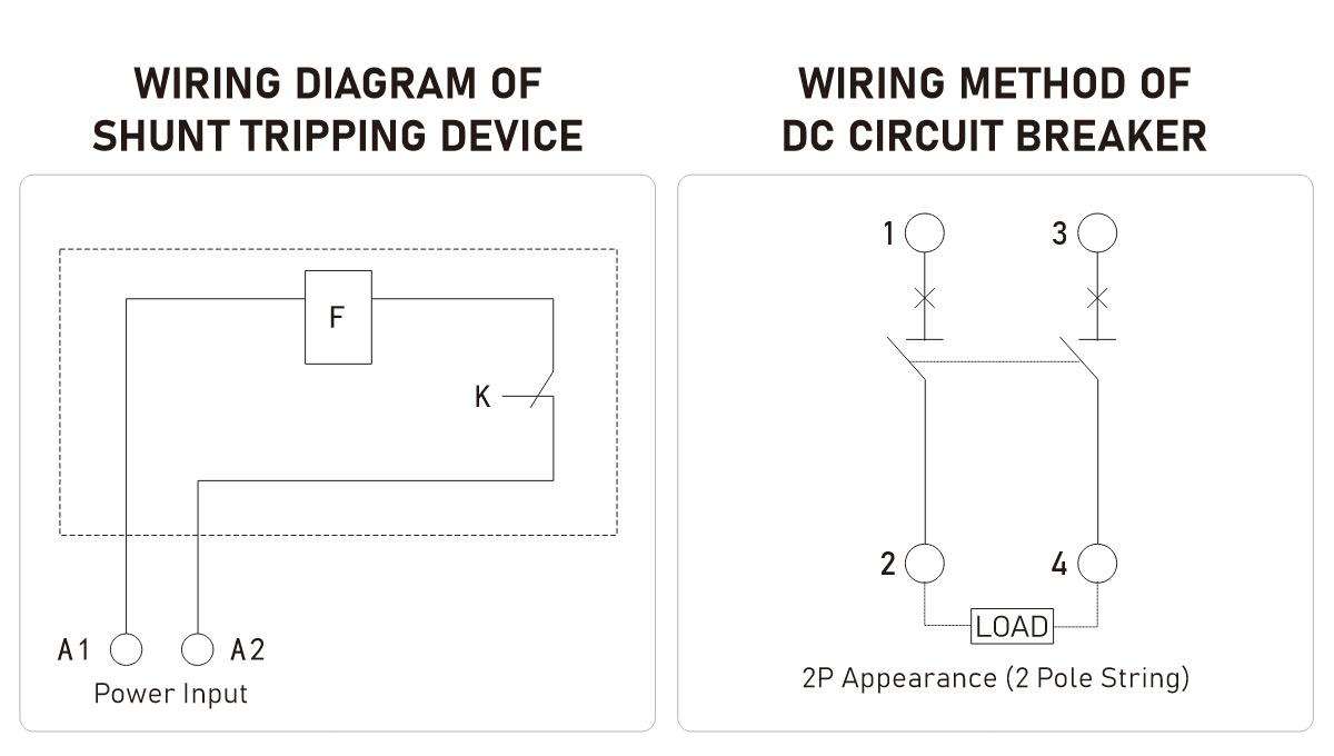
SHUNT TRIPPING DEVICE
Generally installed in phase A of the circuit breaker, when the rated control power voltage is between 70% -110%, the shunt tripping device should reliably trip the circuit breaker under all operating conditions. Conventional control voltage: DC 24V.
Note: When the control circuit power supply is DC24V, it is recommended to use the following diagram for the design of the shunt control circuit.
K: The micro switch connected in series with the coil inside the shunt release is a normally closed contact. When the circuit breaker is opened, the contact automatically opens and closes when the circuit breaker is closed.
| Voltage | Resistance (Ω) | Power (W) |
| DC 24V | 3.8 | 152 |
APPEARANCE AND DIMENSIONS
SAFETY DISTANCE DURING CIRCUIT BREAKER INSTALLATION
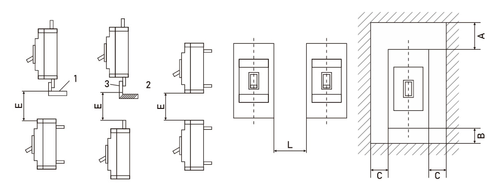
| Model | L | A | B | C | E |
| TXM3Z-125 | 40 | 50 | 25 | 25 | 50 |
| TXM3Z-320 | 100 | 25 | 25 | 100 | |
| TXM3Z-400 | 70 | 50 | 25 | 25 | 50 |
| TXM3Z-800 | 100 | 25 | 25 | 100 |
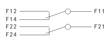
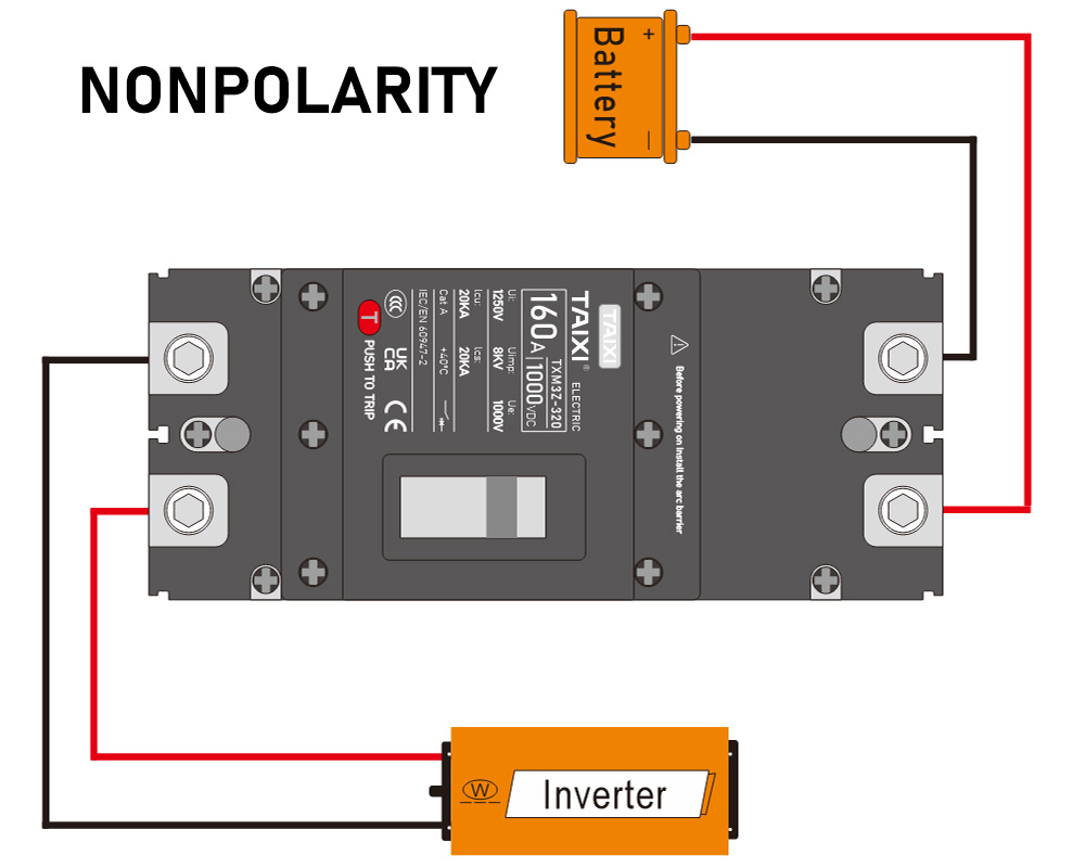
WIRING DIAGRAM


view and download
| File name(Click to view) | File type | file size | View times | Click to download |
Product related news
| News title | Promulgator | Release time | View times | Click to read |