


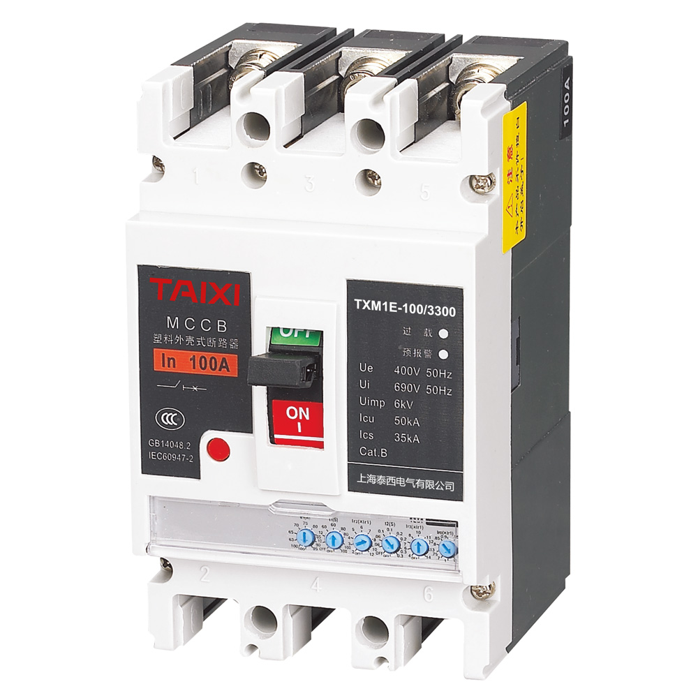


TXCM1E molded case circuit breaker
Miniature Circuit Breaker | MCB


Parameters
Details
Size&weight
Related
Video
Message
SCOPE OF APPLICATION
TXCM1E lv Current adjustable circuit breaker (hereinafter referred to as circuit breaker), the circuit breaker has small size, high breaking capacity, short arc, anti vibration. Its rated insulation voltage is 800V, suitable for the distribution network of AC 50Hz, rated voltage AC400V, rated current up to 1250A and below, used to distribute electrical energy and protect the circuit and power equipment from overload, short-circuit, undervoltage and other faults. It can also be used for the infrequent conversion of the line and the infrequent starting of the motor. The circuit breaker can be vertically installed, or horizontally installed. The lv circuit breaker has isolation function.
MAIN FEATURES
TXCM1E adjustable electronic moulded case circuit breaker has three protection function, the circuit breaker with utilization category B connected with other short-circuit protection device in the same circuit has completely optional under short circuit circumstance; With five tripping features, the user can set the equipment through the shunt release according to the load current, electronic shunt release is powered by circuit breaker itself; current signal and control power is from the circle circuit transformer installed in the circuit breaker; With fire protection shunt release for alarming but not trip, when the load current is overloaded, the circuit breaker does not trip, and output the passive contact, driving the corresponding alarm device; The dimensions and specifications are the same as those of TXCM1 MCCB, the installation can be changed.
NORMAL SERVICE CONDITIONS AND INSTALLATION CONDITIONS
1. The elevation of the installation site is not more than 2000m. 2. The ambient temperature is not more than +40℃, and the average temperature within 24h is not more than +35℃, the lower limit of the ambient temperature is -5℃. 3. When the max temperature is +40℃, the relative humidity of air is not more than 50%, can allow a higher relative humidity at a lower temperature, such as 90% at 20℃, special measures should be taken for the condensation produced occasionally on the product due to temperature changes. 4. The pollution degree is 3. 5. The circuit breaker installation of main circuit category is class III, the installation category of auxiliary circuit and control circuit not connect to the main circuit is II. 6. Use category is A or B
MAIN TECHNOLOGY PARAMETERS
The Setting Range Of Intelligent Controller Is Shown In The Table
| Setting Project | Setting Range | |
| Setting value of overload long delay | Current setting value lr1 | (30~100)A,(100~250)A,(200~400)A,(400~630)A,(630~800)A,(800~1250)A |
| Time setting value t1 | (12、60、80、100)s | |
| Setting value of short circuit and short delay | Current setting value lr2 | (2~12)In |
| Time setting value t2 | (0.06, 0.1, 0.2, 0.3)s | |
| Setting value of instantaneous short circuit | Current setting value lr3 | (4~14)In |
SHORT-CIRCUIT INSTANTANEOUS PROTECTION ACTION CHARACTERISTICS
| Rated Current | 100, 225(250) | 400, 630 | 800 |
| Setting Current | Ir3=4, 6, 7, 8, 10, 11, 12, 13, 14 |
Ir3=4, 6, 7, 8, 10, 11, 12, 13,14 |
Ir3=4, 5, 6, 7, 8, 9, 10, 11, 12 |
| Operation Characteristics | I≤0.85Ir3 non-operation I≤1.15Ir3 operation |
||
THE MAIN TECHNICAL DATA OF CIRCUIT BREAKER ARE SHOWN IN TABLE
| Model | TXCM1E-100 | TXCM1E-250 | TXCM1E-400 | TXCM1E-630 | TXCM1E-800 | TXCM1E-1250 | ||||||
| TXCM1E-1250 | 100 | 250 | 400 | 630 | 800 | 1250 | ||||||
| Breaking Capacity | L | M | L | M | L | M | M | H | M | H | M | |
| Rated Current In(A) | 63,80,100 | 225,250 | 300,400 | 500,630 | 700,800 | 1000,1250 | ||||||
| Pole | 3,4 | 3,4 | 3,4 | 3,4 | 3,4 | 3,4 | 3,4 | 3,4 | 3,4 | 3,4 | 3,4 | |
| Rated Operational Voltage Ue (V) | AC400 | |||||||||||
| Rated Insulation Voltage Ui (V) | 800 | |||||||||||
| Rated Insulation Voltage Ui (V) | 8000 | |||||||||||
| Rated limit short circuit breaking capacity Icu (kA) | 50 | 85 | 50 | 85 | 65 | 100 | 65 | 100 | 65 | 100 | 80 | |
| Rated running short circuit breaking capability Ics (kA) | 30 | 50 | 30 | 50 | 42 | 65 | 42 | 62 | 42 | 62 | 50 | |
| Rated short-time withstand current Icw/0.5s (kA) | - | - | 5 | 8 | 10 | 15/1S | ||||||
| Usage Category | A | A | B | B | B | B | ||||||
| Flashover Distance (mm) | ≤50 | ≤50 | ≤100 | ≤100 | ≤100 | |||||||
| Operatig Performance | Power-on (Times) | 1500 | 1000 | 1000 | 500 | 500 | 500 | |||||
| Power-off (Times) | 8500 | 7000 | 4000 | 3000 | 3000 | 3000 | ||||||
Characteristics Of Release
a. Characteristics of Electric Trip Unit
With overload long-delay inverse time, short-circuit short-delay inverse time, short-circuit short delay time limit,
short-circuit instantaneous action and other protection features, the protection characteristics can be set up by
the users.
b. Overload long delay inverse time protection action characteristics in Table 4.
c. Short-circuit short-delay protection action characteristics in Table 5.
d. Short-circuit instantaneous protection action characteristics in Table 6.
| Controller Types | Basic type | Intelligent communication type, programming communication type, liquid crystal type | |
| Current | Action Time | ||
| 1.05lr1 | No action within 2 hours | ||
| 1.3lr1 | ≤1h action | ||
| 2lr1 | Inm=100A, 250A Setting time t1(s) | t1=(12, 60, 80, 100)s | t1=(12, 60, 80, 100)s |
| Inm=400A, 630A, 800A Setting time t1(s) | t1=(12, 60, 80, 100)s | 12s-100s(most progress 1s) | |
| Thermal Memory | 30min, can be cleared after power off (this function is optional function in intelligent communication type and programming communication type) | ||
1. Action time I²t1 = (2Ir1) ²t1 (1.2Ir1≤I 2. Action time tolerance is ± 20%;
3. Returnable time is not less than 70% action time.
Short delay overcurrent protection characteristics
| Current | Action Time | |||||
| Ir2≤I<1.5Ir2 | Ir2≤I<1.5Ir2 | I²t2=(1.5Ir2)²t2 | ||||
| 1.5Ir2≤I<Ir3 | Definite time | Setting time t2(s) | 0.06 | 0.1 | 0.2 | 0.3 |
| Tolerance (s) | ±0.02 | ±0.03 | ±0.04 | ±0.06 | ||
| Returnable time (s) | 0.21 | |||||
Note: Inverse time action time tolerance is ± 20%.
TECHNICAL DATA OF ACCESSORY DEVICE
a. Rated values of auxiliary contacts and alarm contacts are shown in table
| Type | Frame Rated Current Inm(A) |
Conventional Thermal Current Ith(A) |
Rated Operational Current Ie(A) | |
| AC400V | DC220V | |||
| Auxiliary Contact | Inm≤400 | 3 | 0.3 | 0.15 |
| Inm≥400 | 3 | 0.4 |
0.15 |
|
| Auxiliary Contact | 100≤Inm≤800 | 3 | 0.3 | 0.15 |
b. The rated control power supply voltage (Us) and rated operating voltage (Ue) of the control circuit release and electric mechanism are shown in Table 8
| Type | Rated Voltage (V) | |||
| AC50Hz | DC | |||
| Release | Shunt Release | Us | 220/380 | 110、220 |
| Undervoltage Release | Ue | 220/380 | - | |
| Electric Mechanism | Us | 220/380 | 110、220 | |
c. When the applied voltage of the shunt release is between 70%~100% of the rated power voltage, the circuit breaker should be reliably broken.
d. When the power voltage drops to 70% ~ 35% of the rated voltage of the undervoltage release, the undervoltage release can reliably break the circuit breaker; When the power voltage is lower than 35% rated voltage of the undervoltage release, the undervoltage release can prevent the circuit breaker from closing; When the power voltage is higher than 85% rated voltage of the undervoltage release, the undervoltage release can ensure the reliable closing of the circuit breaker.
e. Electric operating mechanism at the rated frequency, between 85% ~ 110% power voltage, the circuit breaker can be reliably closed.
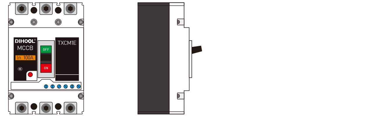
OUTLINE AND INSTALLATION DIMENSIONS
1. The dimensions are shown in figure 3~figure 6 and the table
(1) Dimensions of front connection see Figure 3 (X-X, Y-Y is the center of 3P circuit breaker)
| Model | TXCM1E-100 | TXCM1E-250 | TXCM1E-400 | TXCM1E-630 | TXCM1E-800 | |
| Front Connection | W | 82 | 107 | 150 | 210 | |
| W1 | 60 | 70 | 96 | 140 | ||
| L | 150 | 165 | 257 | 280 | ||
| L1 | 100 | 132 | 220 | 240 | ||
| L2 | 132 | 144 | 244 | 243 | ||
| H | 93 | 90 | 107 | 116 | ||
| H1 | 112 | 110 | 147 | 155 | ||
| H2 | 29 | 24 | 38 | 46 | ||
| H3 | 12 | 5 | 9.5 | 15 | ||
| H4 | 4 | 4 | 6.5 | 5 | ||
| E | 55 | 65 | 92 | 83 | ||
| F | 25 | 25 | 68 | 68 | ||
| G | 18 | 22 | 30 | 44 | ||
| W2 | 122 | 142 | 198 | 280 | ||
| W3 | 90 | 105 | 144 | 210 | ||
| MB | MB | M10 | M10 | M12 | ||
(2)Dimensions of rear connection see Figure 4 and 5
(3) Dimensions of plug-in type front connection see Figure 6
(4)Dimensions of plug-in type rear connection see Figure 7
| Model | TXCM1E-100 | TXCM1E-250 | TXCM1E-400 | TXCM1E-630 | TXCM1E-800 | |
| Rear Connection | L4 | 184 | 173 | 267 | 295 | |
| H5 | 53 | 55 | 68 | 84 | ||
| H6 | 93 | 100 | 128 | - | ||
| H7 | 35 | 35 | 37 | 37 | ||
| M1 | M8 | M8 | M10 | M10 | M12 | |
| d | - | 8.5 | 10.5 | 13 | ||
| t | - | - | 8.5 | 13 | ||
| Rear Connection | L6 | 168 | 183 | 279 | 296 | |
| H8 | 50 | 50 | 60 | 61 | ||
| H9 | 64 | 72 | 84 | 87 | ||
| H10 | 76 | 87 | 107 | 148 | ||
| H11 | 18 | 18 | 21 | 16 | ||
| M1 | M8 | M8 | M10 | M10 | M12 | |
| M2 | M6 | M6 | M6 | M8 | M8 | |
| L7 | 220 | 252 | 357 | - | ||
| L8 | 250 | 276 | 387 | - | ||
2. DIMENSIONS FOR MOUNTING PLATE OPENING
(1)Dimensions of front connection see Figure 8 (X-X, Y-Y is the center of 3P circuit breaker)
| Model | TXCM1E-100 | TXCM1E-250 | TXCM1E-400 | TXCM1E-630 | TXCM1E-800 | |||||
| Pole | 3 | 4 | 3 | 4 | 3 | 4 | 3 | 4 | 3 | |
| Dimensions for mounting plate opening (mm) | A | 30 | 35 | 44 | 70 | 70 | ||||
| B | 129 | 126 | 194 | 243 | 303 | |||||
| d | 4.5 | 4.5 | 7 | 7 | 7 | |||||
(2) Dimensions of rear connection see Figure 9 (X-X, Y-Y is the center of 3P circuit breaker)
| Model | TXCM1E-100 | TXCM1E-250 | TXCM1E-400 | TXCM1E-630 | TXCM1E-800 | ||||||
| Pole | 3 | 4 | 3 | 4 | 3 | 4 | 3 | 4 | 3 | 4 | |
| Dimensions for mounting plate opening (mm) | A | 60 | - | 70 | - | 96 | - | 140 | - | ||
| A1 | - | 90 | - | 105 | - | 144 | - | 210 | |||
| B | 72 | - | 87 | - | 124 | - | 178 | - | |||
| B1 | - | 102 | - | 122 | - | 172 | - | 248 | |||
| C | 90 | 93 | 164 | 158 | |||||||
| D | 132 | 144 | 224 | 243 | |||||||
| Φ1 | 22 | 24 | 32 | 48 | |||||||
| Φ2 | 55 | 55 | 65 | 7 | |||||||
| Model | TXCM1E-100 | TXCM1E-250 | TXCM1E-400 | |
| Pole | 3 | 3 | 3 | |
| Dimensions for mounting plate opening (mm) | A | 92 | 107 | 150 |
| B | 60 | 70 | 60 | |
| C | 56 | 54 | 129 | |
| D | 38 | 63.2 | 62 | |
| E | 92 | 94 | 109 | |
| d | 6.5 | 6.5 | 8.5 | |
| Model | TXCM1E-100 | TXCM1E-250 | TXCM1E-400 | TXCM1E-630 | TXCM1E-800 | ||||||
| Pole | 3 | 4 | 3 | 4 | 3 | 4 | 3 | 4 | 3 | 4 | |
| Dimensions for mounting plate opening (mm) | A | 94 | - | 110 | - | 152 | - | 215 | - | ||
| A1 | - | 125 | - | 145 | - | 200 | - | 283 | |||
| B | 60 | - | 70 | - | 60 | - | 140 | - | |||
| B1 | - | 90 | - | 105 | - | 108 | - | 210 | |||
| C | 56 | 54 | 129 | 143 | |||||||
| D | 48 | 58 | 65 | 65 | |||||||
| E | 90 | 88 | 166 | 183 | |||||||
| d | 6.5 | 6.5 | 8.5 | 10 | |||||||
OUTLINE AND INSTALLATION DIMENSIONS

view and download
| File name(Click to view) | File type | file size | View times | Click to download |
Product related news
| News title | Promulgator | Release time | View times | Click to read |