


Parameters
Details
Size&weight
Related
Video
Message
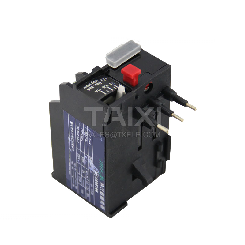
Product Overview
JR29 (T) Thermal Relay Switch (hereinafter referred to as thermal relay) is suitable AC electric power system with AC 50Hz, voltage to 660V, current of 0.1-500A. It is generally used for the protection of overload and phase failure of general AC motor in long-term or intermittent long-term. And it is often made up electromagnetic starters with CJX8 series AC contactors.
Products meet the GB14048.4 standard.
Products meet the GB14048.4 standard.
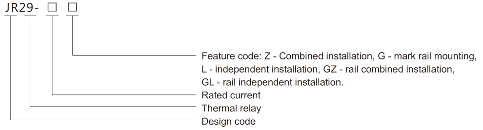
Model and Meaning
Normal working conditions and installation conditions
Ambient temperature: -5℃+40℃, the average value does not exceed +35°C in 24 hours.
Altitude: no more than 2000m.
Atmospheric conditions: The relative humidity does not exceed 50% at +40°C, and higher relative humidity may be allowed at lower temperatures. For example, 90% at 20°C, special measures should be taken for the occasional condensation due to temperature changes.
Pollution level: 3 levels.
Installation category: Class III.
Installation conditions: The inclination of the installation face and the vertical is not more than ±5°.
In addition to mounting screws, the relay can also use 35mm standard rail.
Shock vibration: The relay should be installed and used in places where there is no significant shaking, shock and vibration.
Transportation, Storage: The relay should not be subject to severe impact and vibration during transportation, and it must not be affected by rain or snow in transportation and storage. Relays are suitable for transport and storage at -25°C ~ +55°C, and at +70°C for short periods (in 24h).
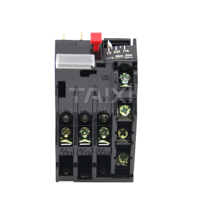
Structure Feature
Internal structure: insert combination typederive or independent type, independent type can be derived from insert type; with phase failure and temperature compensation structure.
Installation operation: cut off test button of the normally closed contact, and has the action instructions, free tripping function; can convert manual reset (JR29-16), auto reset (JR29-85), current transformer (JR29-250/370); independent, insert and guide rails and other installation methods; setting current continuously adjustable.
Installation operation: cut off test button of the normally closed contact, and has the action instructions, free tripping function; can convert manual reset (JR29-16), auto reset (JR29-85), current transformer (JR29-250/370); independent, insert and guide rails and other installation methods; setting current continuously adjustable.
Main Technical Parameters
Adjustable range of setting current
The action characteristics when each phase load is balance (20℃)
The action characteristics when each phase load is unbalance (20℃)
Trip Level: Level 10A: JR29-16, JR29-25, JR29-45
Level 10: JR29-85XJR29-105\JR29-17CKJR29-250XJR29-370
Adjustable range of setting current
Length and cross section of the main circuit connecting wire
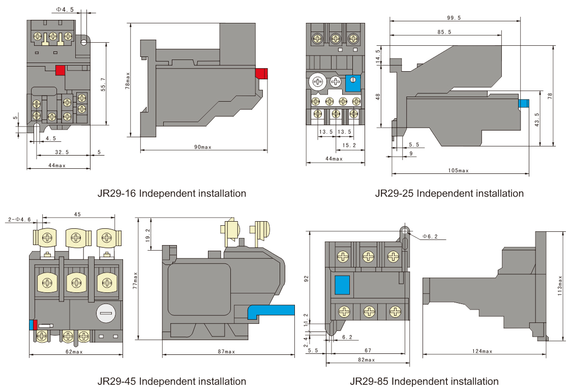
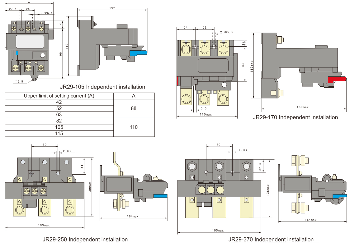
Outline and lnstallation Dimension
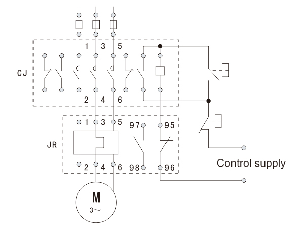
Wiring diagram of circuit principle

view and download
| File name(Click to view) | File type | file size | View times | Click to download |
Product related news
| News title | Promulgator | Release time | View times | Click to read |