


TXQ6 Automatic Transfer Switch
Transfer Switch


Parameters
Details
Size&weight
Related
Video
Message
Scope of Application
TXQ6 Automatic Transfer Switch, TSE-type PC-class; for power supply system of AC 50Hz, AC rated voltage of 380V, rated current of 3150A, three-phase four-wire.
To achieve automatic and manual switching between common and standby power supply, in the process of switching power supply, to cut off the power supply to the load.
Used for the occasion with requirements of two-way power supply and high power quality. There are 16A~200amp automatic transfer switch and 250A~3150A switches produced.
TXQ6 Automatic Transfer Switch complies with GB 14048.3 and GB 14048.11, IEC 60947-3 and IEC 60947-6-1 standards.
Model and its meaning

Normal operating conditions and installation conditions
3.1 The ambient air temperature is not higher than +40 ℃, not lower than -5 ℃.
3.2 The altitude of the installation site shall not exceed 2000m.
3.3 Humidity: the maximum temperature of +40 ℃, the relative humidity of air does not exceed 50%, at a lower temperature can allow a higher.
Relative humidity, for example 90% at 20 & lt; 0 & gt; C. Special precautions should be taken for condensation that may occur occasionally as a result of temperature changes.
3.4 The pollution level of the surrounding environment is Grade 3.
3.5 Transfer Switch should be installed in the absence of significant shaking, shock and no rain and snow invasion of the place, while the installation site should be no explosion hazard medium, and the media is not enough to corrode the metal and damage the insulation of gases and dust.
Main parameters and technical performance
Control characteristics and product structure
5.1 Control characteristic:
5.1 Control characteristic:
The switch has three-pole, four-pole (three-pole + neutral pole can be on or off) product.
Four types of control (common type, Ⅰ, Ⅱ, Ⅲ), commonly used is "common type".
Operation mode of the automatic conversion operating mechanism is selected by the key switch, and the position can be maintained by the padlock.
Control characteristic of common-type switch:
Switch is used for the automatic change and automatic recovery of main power supply - standby power supply system.
Control characteristic of Ⅰ-type switch:
Switch is used for the automatic change and non-automatic recovery, mutual standby of electric supply - electric supply main-standby power supply system. The main power to the standby power (Continuous adjustable delay 1~999s),standby power to the main power supply (Continuous adjustable delay 1~999s). There is phase loss detection and over-under voltage protection function.
Control characteristic of Ⅱ-type switch:
Switch is used for the automatic change and automatic recovery of electric supply - electric supply main-standby power supply system. The main power to the standby power (Continuous adjustable delay 1~999s),standby power to the main power supply (Continuous adjustable delay 1~999s). There is phase loss detection and over-under voltage protection function.
Control characteristic of Ⅲ-type switch:
Switch is used for the automatic change and automatic recovery of electric supply - oil machine (have automatic starting and receiving signal function, ordinary oil generators are not available) power supply system.
When the common power supply is applied to the oil machine power supply system, the switch will transmit signal of starting oil machine at first, the oil machine starts after chip warming up (Continuous adjustable delay 0~999s)
Oil machine back to electric supply, the oil machine is closed after cooling machines (Continuous adjustable delay 0 ~ 999s). There is phase loss detection and over-under voltage protection function.
Above three kinds switches of Ⅰ, Ⅱ, Ⅲ have:
1) Automatic, remote control, manual control
2) Delay 0.5s to detect signal, to prevent malfunction.
3) The automatic status has the remote control "0" position.
4) Key switch selects the operating mode.
5.2 Product structure


a. Electric key lock: internal control line power of control switch, the electrical lock is in the "automatic position", the switch achieves automatic, remote control operation, electrical lock is in the "manual" position, the switch can only be manually operated;
b. Operating handle: when using the operating handle to operate the switch, you must close the electrical lock;
c. Mechanical padlock: when maintenance, firstly, use the operating handle to make switch in the 0 position, pull up the padlock structure and padlock, then can be checked: (pulling the mechanical padlock will cut off the internal control power of switch, the switch can not be electric, and can not be manual);
d. Position indication: Indicates the position of the switch operating status (Ⅰ; 0; Ⅱ);
e. Control voltage: switch control voltage level 220VAC;
f. Switch body: the front part is Ⅰ-way, connect to "common power"; the latter part is Ⅱ-way, connect to "standby power."
5.3 Control circuit terminals:
Common type control circuit terminal 16-100A / 4 poles (Eg: TXQ6-100 / 4SZ)

Common type control circuit terminal 16-100A/3-pole, 125-3150/3-pole and 4-pole(Eg: TXQ6-200amp automatic transfer switch /3SZ or 4SZ)
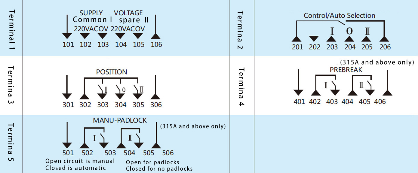
Common type+fire (DC24V) control circuit terminal 16-630A/3-pole and 4-pole (Eg: TXQ6-200 amp automatic transfer switch /3SZ or 4SZ fire-type)

Ⅰ, Ⅱ, Ⅲ control circuit terminal 160-3150/4-pole (Eg: TXQ6-200amp automatic transfer switch /4SZⅠ, Ⅱ or Ⅲ)

Wiring diagram
6.1 Wiring diagram of 16A~100A 4-pole common type main switch

6.2 Wiring diagram of 125A~3150A common type main switch

6.3 Wiring method of No.2 terminal according to different ways is as follows:
a. Automatic wiring mode

b. Wiring mode of remote control and position "0" (double power supply are cut off)

c. Wiring mode of automatic + remote control (Note: SB1, SB2 are the external button switch)

6.4 Wiring Instructions


Main structure and the correct installation method of switch:
(1) The front part is Ⅰ-way, connect to "common power"; the latter part is Ⅱ-way, connect to "standby power".
(2) Operation mode of the automatic conversion operating mechanism is selected by the key switch, and the position can be maintained by the padlock.
(3) The line bank of switch body from left to right is A, B, C, N phase.
(4) The upper end of the main switch is inlet line of Ⅰ-way, Ⅱ-way, the lower end is outlet line of Ⅰ-way, Ⅱ-way with connection of copper busbar or wire connection for the outlet.
Outline and installation dimensions
7.1 Outline and installation dimensions of TXQ6 series switch body

7.2 Outline and installation dimensions of TXQ6H series with box type

7.3 Outline and installation dimensions of TXQ6YFH series with steel casing LCD

Use and maintenance
8.1 The automatic transfer switch should be checked whether nameplates are consistent with requirements before installation, to ensure the switch in the open position.
8.2 The electric key is the control circuit power supply inside the control switch. When the electrical lock starts, the switch can realize automation and remote operation. When the electric lock is closed, the switch can only be operated manually.
8.3 When operating the switch with the operating handle, the electrical lock must be closed.
8.4 When maintenance, firstly, use the operating handle to make switch in the 0 position, pull up the padlock structure and padlock, then can be checked: (pulling the mechanical padlock will cut off the internal control power of switch, the switch can not be electric, and can not be manual).
Switch debugging instructions
9.1 Connect the common power supply (Ⅰ) and the standby power supply (Ⅱ) to the corresponding copper wiring board.
Fully automatic commissioning:
Common power supply with electricity, standby power supply with electricity, the switch is on in Ⅰ-way (Note: I-type switch without this function, being which way power, it should be connected to that way at first)
Common power loss, standby power supply with electricity, the switch is on in Ⅱ-way;
Common power with electricityl, the switch is on in Ⅰ-way (except for Ⅰ-type switch).
(See the switch panel indicator arrows)
Pull the function selector switch to the automatic position: the switch should operate in fully automatic mode;
9.2 When the automatic transfer switch is on in the Ⅰ-way or Ⅱ-way, the signal light on the panel should be indicated accordingly;
9.3 After commissioning, turn off the power firstly, and switch to the "0" position with the handle switch.
Ordering Information
Ordering unit must indicate the type and characteristics of switch, voltage levels, current levels, the number of poles and quantity and others, special orders, please contact our technical department.
For example: TXQ6-200amp automatic transfer switch / 4SZ 380V 10 units
Keywords: 200 amp automatic transfer switch

view and download
| File name(Click to view) | File type | file size | View times | Click to download |
Product related news
| News title | Promulgator | Release time | View times | Click to read |